Low swing domino logic circuits

a logic circuit and low swing technology, applied in logic circuits, logic circuits, logic functions, etc., can solve the problems of domino logic gates that consume more dynamic switching power, display weak noise immunity, and low power and error free operation of domino logic circuits, so as to reduce the upper boundary of voltage swing, reduce pdp, and reduce the effect of power consumption

Active Publication Date: 2010-07-27
WISCONSIN ALUMNI RES FOUND
View PDF7 Cites 12 Cited by
  • Summary
  • Abstract
  • Description
  • Claims
  • Application Information

AI Technical Summary

Benefits of technology

[0010]As discussed above, the domino logic circuit may have the voltage swing at its output be less than the voltage swing at the dynamic node. To accomplish this, the power, ground, or both to the output circuit may be different from the power and ground to the precharge and input circuit. Or, the output low swing domino circuits may utilize transistors, such as NMOS transistors, to reduce the upper boundary of the voltage swing at the output node. The output low voltage swing circuit may permit the optimization of the output node voltage swing, thereby minimizing PDP. Meanwhile, a greater voltage swing, such as full voltage swing, may be maintained at the dynamic nodes for high speed operation.

Problems solved by technology

However, the domino logic gates used in the domino logic circuit typically consume more dynamic switching power and display weaker noise immunity as compared to the static CMOS gates used in the static CMOS circuits.
The low power and error free operation of domino logic circuits is a major challenge in the current CMOS technologies.
The dynamic switching power consumption of a domino gate is, therefore, higher than a static CMOS gate.
Others have attempted similar low swing domino circuits that suffer from a variety of problems including degraded evaluation speeds and in achieving a smaller area overhead.
Further, the power-delay product (PDP) issue is not addressed.
Although the dynamic switching power is reduced, the output inverter is always simultaneously turned on, thereby producing significant short-circuit current.

Method used


Image

  • Low swing domino logic circuits
  • Low swing domino logic circuits
  • Low swing domino logic circuits

Examples


Embodiment Construction

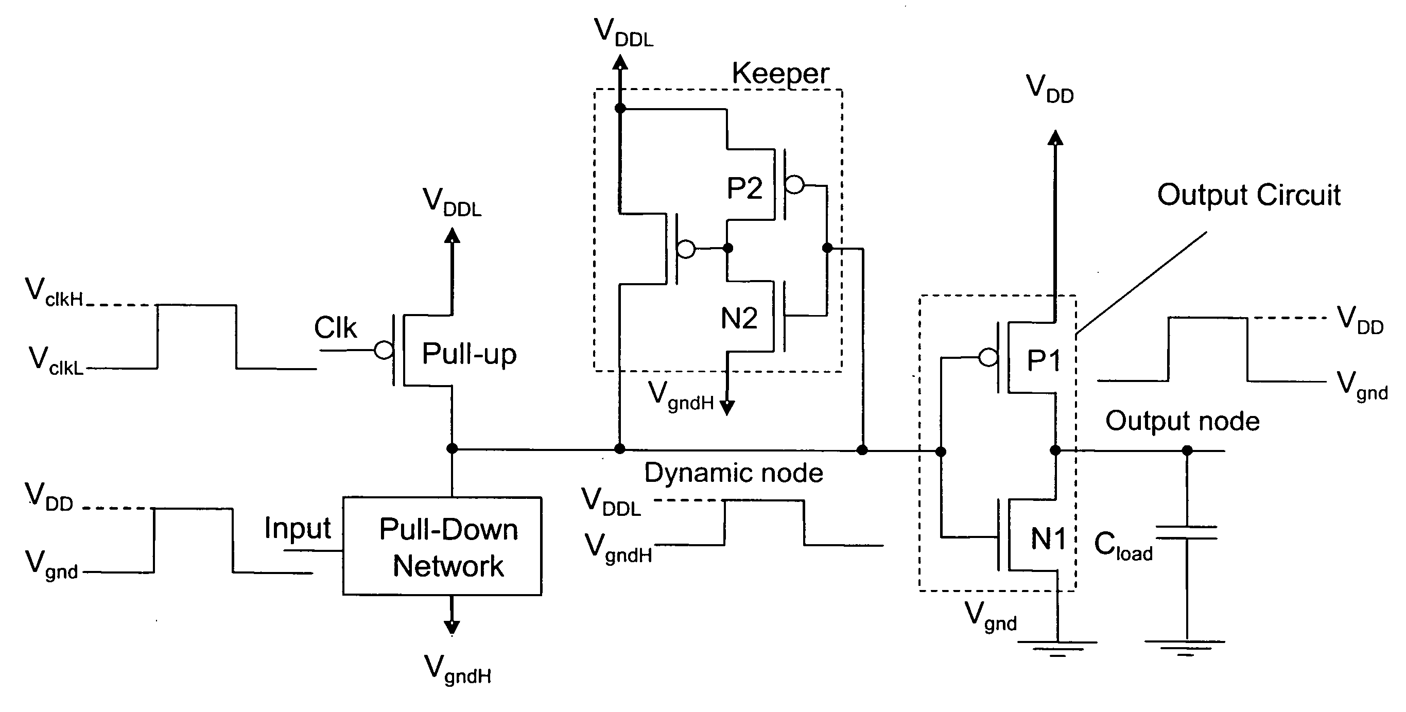
[0048]Low swing domino logic circuits are provided. The circuits may modify the upper and / or lower boundaries of the voltage swing at the dynamic node while maintaining full voltage swing signals at the inputs and outputs for high speed operation. These circuits may significantly reduce the energy required to charge / discharge the dynamic node of a domino gate without significantly increasing the evaluation delay. Further, the circuits may reduce the PDP and enhance the noise immunity.

[0049]In one aspect, the circuit comprises separate power and / or ground supplies for various portions of the circuit. One example of separate power and / or ground supplies is depicted in FIGS. 4 and 5. Specifically, the schematics of bidirectional dynamic node low voltage swing circuits utilizing dual power supply and ground voltages are shown in FIGS. 4 and 5. Referring to FIG. 4, there is shown a schematic of a footless bidirectional dynamic node low voltage swing domino logic circuit with dual power s...


PUM


Abstract

Low voltage swing techniques are provided for simultaneously reducing the active and standby mode power consumption and enhancing the noise immunity in domino logic circuits. One or both the upper and lower boundaries of the voltage swing at the dynamic node may be different from the upper and lower boundaries of the voltage swing at the output node. Further, the domino logic circuit may use dual Vt thereby reducing the short-circuit current during operation. Meanwhile, full voltage swing signals may be maintained at the inputs and outputs for high speed operation. The low swing circuit techniques are provided that modify the output voltage swing of a domino gate, thereby reducing the active mode power consumption.

Description

PRIORITY CLAIM[0001]This application claims the benefit of priority from U.S. Provisional Application No. 60 / 764,741, filed Feb. 1, 2006, which is incorporated by reference herein in its entirety.FIELD[0002]The present application relates to a method and apparatus for reducing the voltage swing for a logic circuit and more specifically, a method and apparatus for reducing the voltage swing for a domino logic circuit to reducing the active and standby mode power consumption and enhance the noise immunity.BACKGROUND[0003]Domino logic circuit techniques have been used in modern high performance microprocessors because of the superior speed and area characteristics of the dynamic circuits as compared to the static CMOS circuits. However, the domino logic gates used in the domino logic circuit typically consume more dynamic switching power and display weaker noise immunity as compared to the static CMOS gates used in the static CMOS circuits. The low power and error free operation of dom...

Claims


Application Information

Patent Timeline
Patent Type & Authority Patents(United States)
IPC IPC(8): H03K19/096
CPCH03K19/0966
Inventor KURSUN, VOLKANLIU, ZHIYU
Owner WISCONSIN ALUMNI RES FOUND
Why Eureka
Try Eureka