Compound domino logic circuit having output noise elimination

a logic circuit and domino logic technology, applied in logic circuits, pulse techniques, reliability increasing modifications, etc., can solve the problems of charge sharing problems at the nodes, impracticality of stacking more than four input transistors,

Inactive Publication Date: 2001-01-09
IBM CORP +1
View PDF19 Cites 5 Cited by
  • Summary
  • Abstract
  • Description
  • Claims
  • Application Information

AI Technical Summary

Problems solved by technology

However, due to current technology limitations, it is impractical to stack more than four input transistors in a simple domino logic circuit configuration for supporting a large number of inputs; hence typically, a compound domino logic circuit structu

Method used


Image

  • Compound domino logic circuit having output noise elimination
  • Compound domino logic circuit having output noise elimination
  • Compound domino logic circuit having output noise elimination

Examples


Embodiment Construction

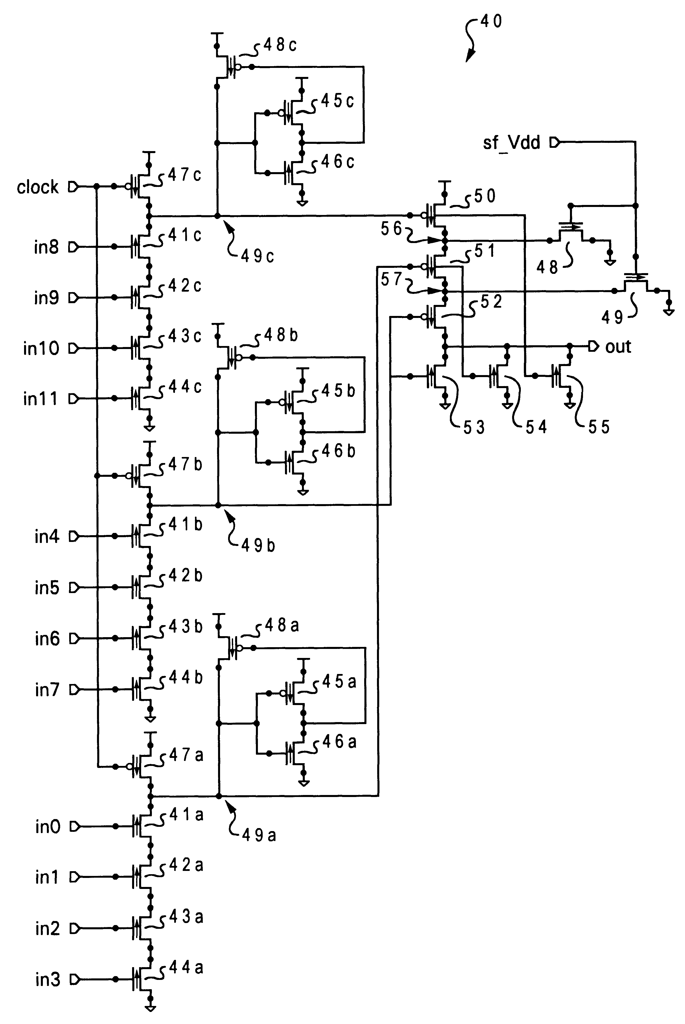
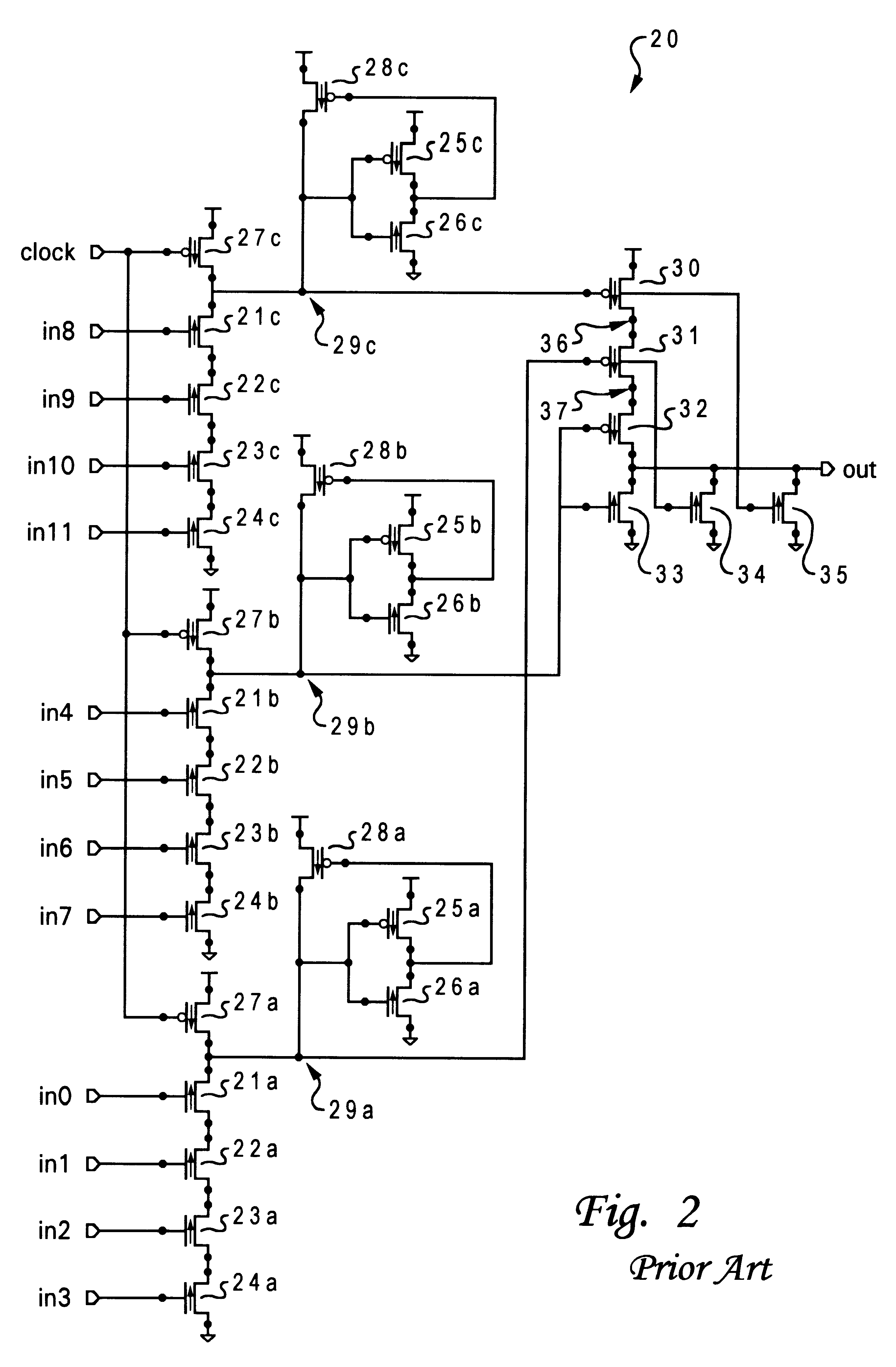
In high performance processor control and data flow structures, it is quite common for logic gates, such as AND, OR, and their combinations, to have a large number of inputs. However, it is impractical to stack more than four or five transistors in a simple domino logic circuit configuration for providing such a large number of inputs. Thus, a compound domino logic circuit structure having a large fan-in is utilized instead. Although compound domino logic circuits have some advantages over simple domino logic circuits, the speed of compound domino logic circuit outputs is relatively slower, particularly when p-channel transistors are stacked together, such as in an AND gate implementation.

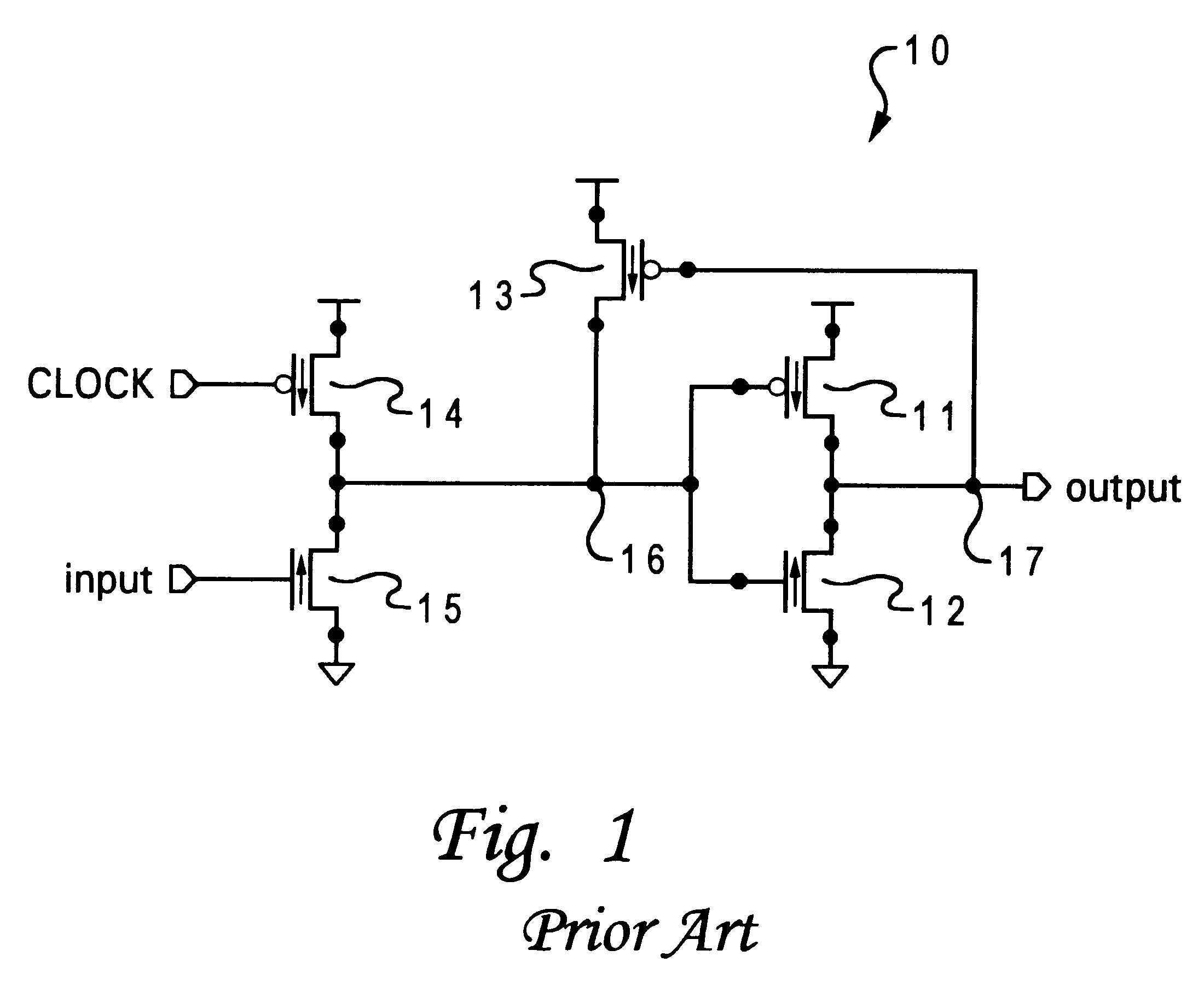
Referring now to the drawings and in particular to FIG. 1, there is illustrated a conventional simple domino logic circuit having a single output. Conventional simple domino logic circuit 10 includes a pull-down n-channel transistor 15 and an output inverter formed by a p-channel transistor 11 and ...


PUM


Abstract

A domino logic circuit having output noise elimination is disclosed. A compound domino logic circuit includes at least two trees of logic devices arranged in parallel, with each tree having a precharge transistor connected to a power supply, and one or more input transistors coupled between the precharge transistor and ground. The precharge transistor receives a clock input while each of the one or more input transistors receives a signal input. The compound domino logic circuit also includes a logic gate coupled to the precharge transistor to produce a signal output. The logic gate includes at least two transistors connected in series. Further, an adjustment transistor is coupled to a node between the two transistors to ground.

Description

1. Technical FieldThe present invention relates to semiconductor circuits in general, and in particular to domino logic circuits. Still more particularly, the present invention relates to a compound domino logic circuit having output noise elimination.2. Description of the Prior ArtA domino logic circuit simplifies digital logic by connecting a number of transistors together in series to implement digital combination logic. For example, a domino logic circuit implements a logic AND function by cascading a p-channel transistor with several n-channel input transistors in series between a power supply and ground. During operation, the p-channel transistor is clocked to precharge an output node of the circuit to a predetermined logic state. Depending on the logic state at the inputs of the n-channel input transistors, the output node either remains at its precharged state or is pulled low through the series of n-channel input transistors connected to ground.It is quite common for logic ...

Claims


Application Information

Patent Timeline
IPC IPC(8): H03K19/096
CPCH03K19/0963
Inventor KLIM, PETER JUERGENDUNNING, JAMES E.
Owner IBM CORP
Why Eureka
Try Eureka