
Error detection in precharged logic

a pre-charged logic and error detection technology, applied in the field of pre-charged logic, can solve the problems of errors that can arise through sources, difficult to use domino logic in small process geometries, and difficult to achieve the effect of reducing the effective capacitance of the speculative node, increasing the magnitude of precharge, and increasing the precharge voltag

Active Publication Date: 2010-09-16
RGT UNIV OF MICHIGAN +1
View PDF7 Cites 6 Cited by
  • Summary
  • Abstract
  • Description
  • Claims
  • Application Information

AI Technical Summary

Benefits of technology

[0010]In some embodiments a transition in the speculative clock signal to a speculative clock signal value that decouples the speculative node from the logic circuitry may also serve to trigger a transition in the checker clock signal to a checker clock signal value that couples the checker node to the logic circuitry. In this way, the relative phase of the speculative clock signal and the checker clock signal may be ensured.
[0017]In some embodiments detection of an error by the error detection circuitry increases the magnitude of precharge, by either increasing the precharge voltage, or increasing the effective capacitance of the speculative node. Increasing the precharge may slow operation and increase energy consumption, but it will tend to make operation more robust.
[0019]The above closed-loop control techniques are useful in that the parameters in operation may be adjusted to suit the individual circuit and its current operating parameter / environment in a way that produces reliable and robust operation without wasteful excessive margining.

Problems solved by technology

However, it is primarily the fundamental design complexity and the necessary compromises between robustness and speed which makes the use of domino logic difficult in small process geometries.
In particular, noise, charge-sharing, leakage and variability, all of which tend to become greater in significance at smaller process geometries, combine to make the practical use of domino logic in small process geometries difficult.
In particular, errors can arise through sources such as late (rising) signals, noise triggering incorrect discharge of domino nodes, inappropriately selected or controlled keeper strength and / or incorrectly controlled or adjusted precharge settings.

Method used


Image

  • Error detection in precharged logic
  • Error detection in precharged logic
  • Error detection in precharged logic

Examples


Embodiment Construction

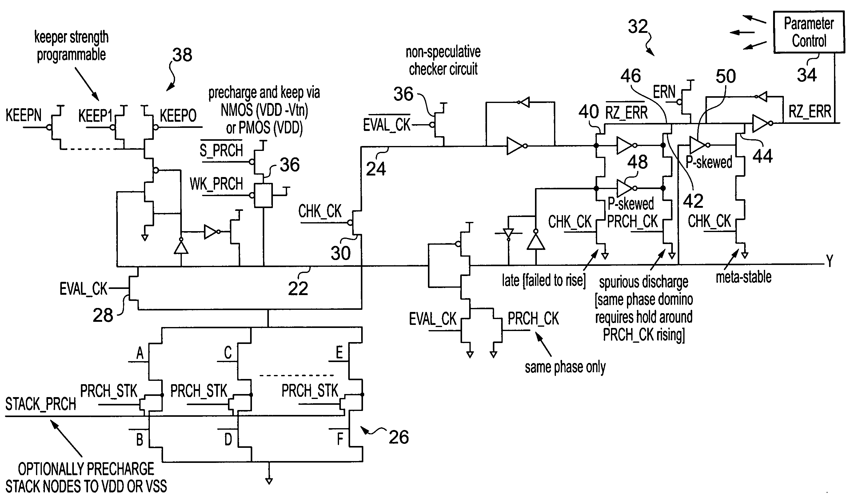
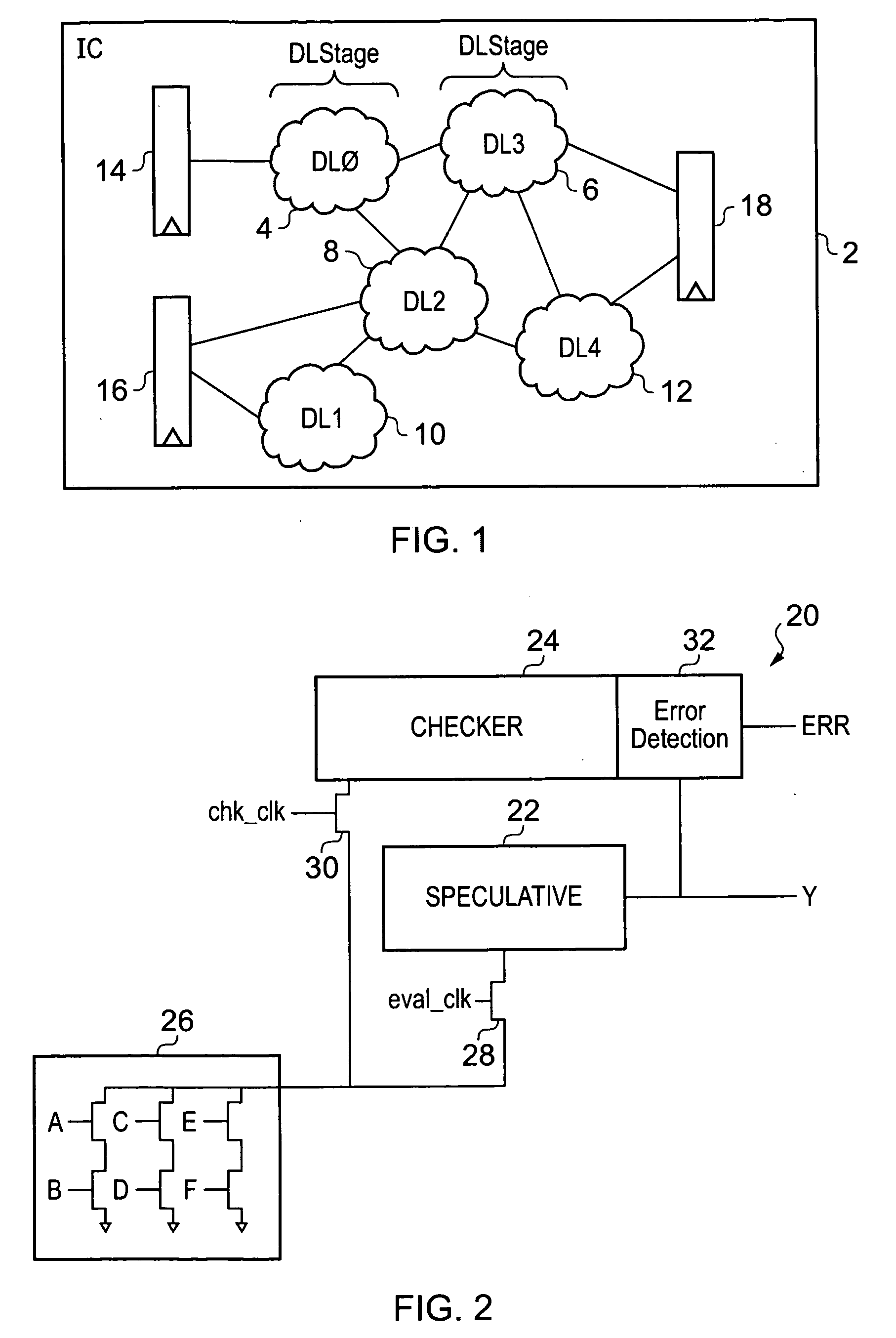
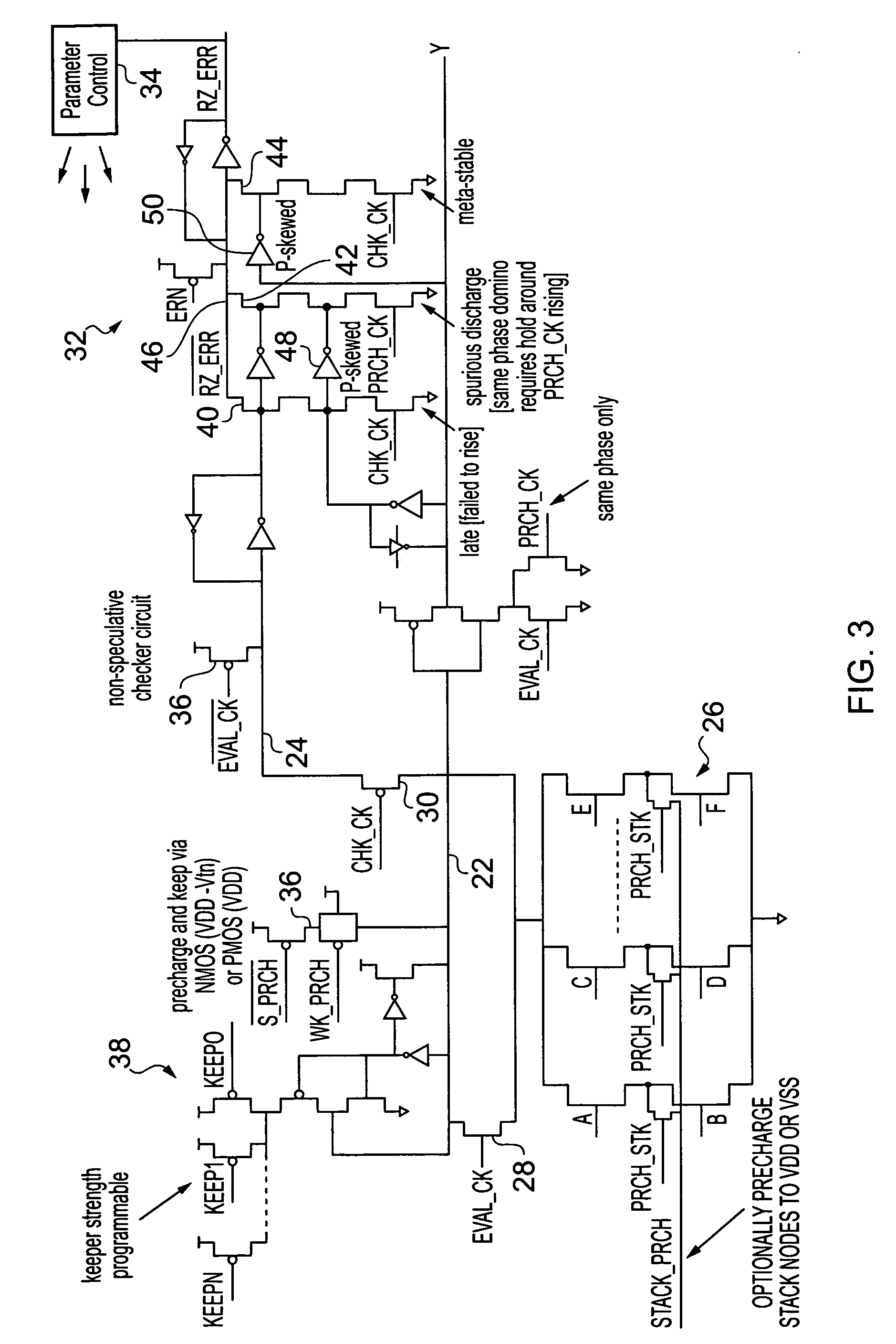
[0039]FIG. 1 illustrates an integrated circuit 2 including multiple processing stages 4, 6, 8, 10, 12 disposed between input registers 14, 16 and an output register 18. It will be appreciated that the integrated circuit 2 will typically contain a large number of such processing stages and only a few of these processing stages have been schematically illustrated. The processing stages 4, 6, 8, 10, 12 are in the form of domino logic processing stages having nodes which are precharged and then selectively discharged depending upon one or more inputs signal to those domino logic processing stages 4, 6, 8, 10, 12. The signals generated by the selective discharge of the nodes within the domino logic go on to form inputs to further stages of domino logic. This type of arrangement of domino logic is in itself known to those in this technical field and will not be described further herein.

[0040]FIG. 2 schematically illustrates a processing stage 20 forming part of domino logic. The processin...


PUM


Abstract

An integrated circuit 2 is provided with domino logic including a speculative node 22 and a checker node 24. Precharged circuitry 36 precharges both the speculative node and the checker node. Logic circuitry 26 provides a discharge path for the speculative node and the checker node in dependence upon input signal values. Evaluation control circuitry 28, 30 first couples the speculative node to the logic circuitry and then subsequently couples the checker node to the logic circuitry such that these can be discharged if the input signals to the logic circuitry 26 have appropriate values. Error detection circuitry 32 detects an error when the speculative node and the checker node are not one of both discharged or both undischarged.

Description

BACKGROUND OF THE INVENTION[0001]1. Field of the Invention[0002]This invention relates to the field of precharged logic, such as, for example, domino logic. More particularly, this invention relates to error detection within such precharged logic.[0003]2. Description of the Prior Art[0004]It is known to provide domino logic in which precharged nodes are discharged in response to combinations of input signals. These nodes generate signals which go onto control the discharge of other nodes. Domino logic has become less widely used in recent times due to a variety of factors including the rapid advance in process technology coupled with continuous improvements in design automation that are better suited to logic designs different to domino logic designs. While domino logic is inherently well suited to high speed operation, this advantage has been reduced compared to standard CMOS logic. However, it is primarily the fundamental design complexity and the necessary compromises between rob...

Claims


Application Information

Patent Timeline
IPC IPC(8): G01R31/3177G06F11/25
CPCG01R31/3177
Inventor BULL, DAVID MICHAELDAS, SHIDHARTHABLAAUW, DAVID THEODORE
Owner RGT UNIV OF MICHIGAN
Learn More