Piezoelectric actuator and lens driving device

a technology of piezoelectric actuator and driving device, which is applied in the direction of piezoelectric/electrostrictive/magnetostrictive devices, mountings, instruments, etc., can solve the problems of reducing the bulk of the piezoelectric actuator, requiring high precision, and complicating the assembling structure and process, so as to save manufacturing costs and reduce the volume. , the effect of small siz

Inactive Publication Date: 2010-07-27
SAMSUNG ELECTRO MECHANICS CO LTD
View PDF10 Cites 19 Cited by
  • Summary
  • Abstract
  • Description
  • Claims
  • Application Information

AI Technical Summary

Benefits of technology

[0022]An aspect of the present invention provides a piezoelectric actuator which is simplified in a manufacturing process to save manufacturing costs and reduced in volume to ensure a smaller size.
[0023]An aspect of the present invention also provides a lens driving device which is simplified in structure to achieve a smaller size and superior in driving resolution due to a sufficient driving distance at a low input voltage, minimized in loss of a driving force, simplified in a guiding mechanism for driving a lens, and can ensure accurate and stable transport of the lens.

Problems solved by technology

However, the conventional piezoelectric actuator entails a complicated process of forming the external electrodes connected to the internal electrode, thus requiring high precision.
This hinders simplification of a manufacturing process for saving manufacturing costs and reduction of the bulk of the piezoelectric actuator.
This complicates an assembling structure and a process, and hinders miniaturization of the product.
However, in this conventional device, the driving rods are fixed so that a length of barrel cannot be changed.
Also, a driving signal of the device is an asymmetrical wave signal, not a sine wave signal, thereby complicating a driving circuit.

Method used


Image

  • Piezoelectric actuator and lens driving device
  • Piezoelectric actuator and lens driving device
  • Piezoelectric actuator and lens driving device

Examples


Embodiment Construction

[0061]Exemplary embodiments of the present invention will now be described in detail with reference to the accompanying drawings.

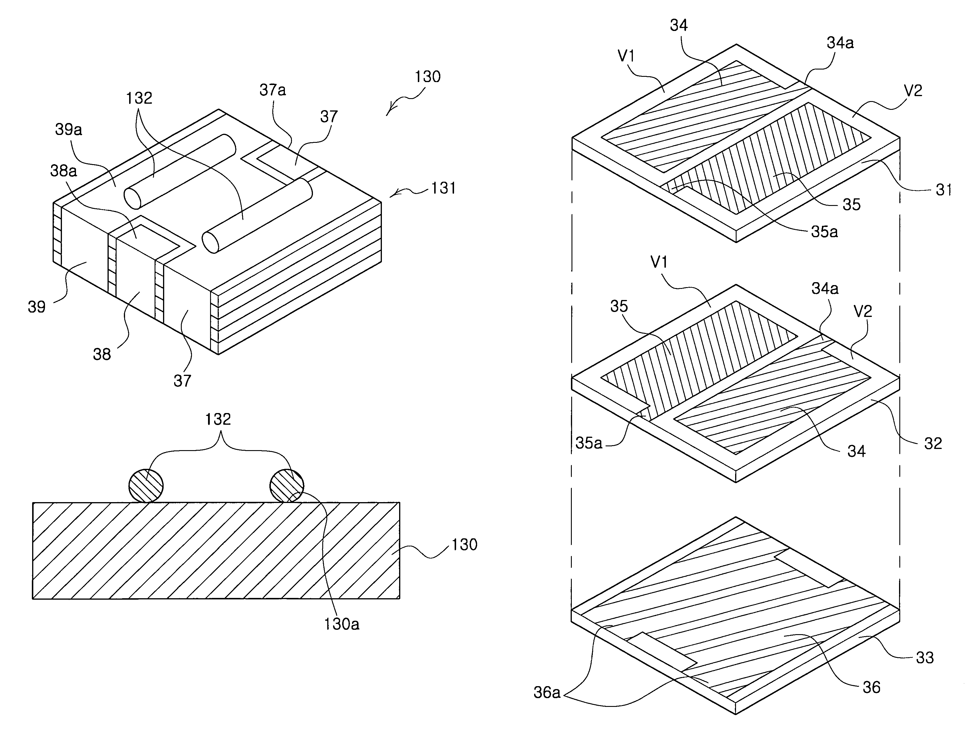
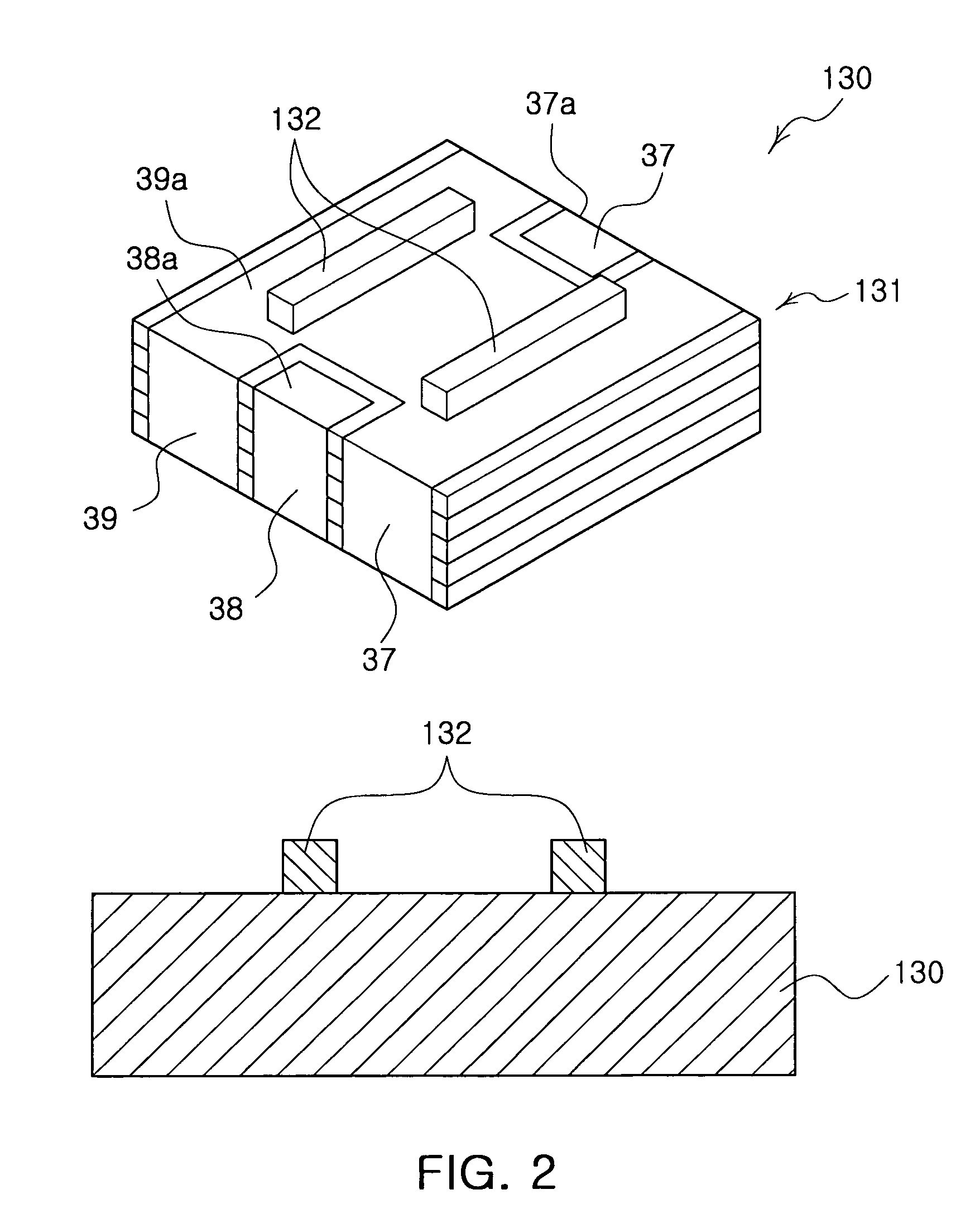
[0062]FIG. 2 is a perspective view illustrating a piezoelectric actuator according to a first embodiment of the present invention. FIG. 3 is a perspective view illustrating a piezoelectric actuator according to a second embodiment of the present invention. FIG. 4 is an exploded perspective view employed in a piezoelectric actuator according to an exemplary embodiment of the invention. FIG. 5 is an exploded perspective view illustrating first and second piezoelectric bodies employed in a piezoelectric actuator according to an exemplary embodiment of the invention.

[0063]The piezoelectric actuator 130 includes a piezoelectric body 131, a friction member 132 and an electrode part 133.

[0064]The piezoelectric body 131 includes first ceramic sheets 31 and 32 having first and second internal electrodes 34 and 35 spaced apart from each other at a predetermined dist...


PUM


Abstract

There are provided a piezoelectric actuator and a lens driving apparatus having the piezoelectric actuator. The lens driving device includes: a lens barrel having a lens hole where at least one lens is disposed, and having a tip friction member on an outer surface thereof; a base having a guiding part guiding the lens barrel to move along an optical axis direction; a piezoelectric actuator having a piezoelectric body disposed at an edge of the base to apply a driving force when a power is applied, the piezoelectric body having at least one friction member at one side thereof to be in contact with the tip friction member; and a preload member applying an elastic force for elastically supporting the piezoelectric actuator against the lens barrel to keep the tip friction member and the friction member in contact with each other.

Description

CROSS-REFERENCE TO RELATED APPLICATIONS[0001]This application claims the priority of Korean Patent Application No. 2007-52088 filed on May 29, 2007, in the Korean Intellectual Property Office, the disclosure of which is incorporated herein by reference.BACKGROUND OF THE INVENTION[0002]1. Field of the Invention[0003]The present invention relates to a piezoelectric actuator and an apparatus for driving a lens applied to an optical device using the piezoelectric actuator, and more particularly, to a piezoelectric actuator which is simplified in a driving mechanism to achieve a smaller size, minimized in loss of a driving force for driving a lens and ensures more accurate and stable transport of the lens.[0004]2. Description of the Related Art[0005]In general, an optical apparatus includes a lens driving device for driving a lens. This lens driving device employs an actuator such as an electromagnetic motor or a piezoelectric actuator to generate a driving force, and a cam or a screw to...

Claims


Application Information

Patent Timeline
Patent Type & Authority Patents(United States)
IPC IPC(8): G02B7/02G02B15/14G02B7/04H01L41/083H01L41/22H01L41/293H01L41/297H02N2/00
CPCG02B7/08H01L41/0913H02N2/026H01L41/083H10N30/2023H10N30/50H02N2/02
Inventor KOC, BURHANETTINKO, HYUN PHILL
Owner SAMSUNG ELECTRO MECHANICS CO LTD
Why Eureka
Try Eureka