Surveying method and surveying instrument

a technology of surveying method and surveying instrument, which is applied in the field of surveying instruments, can solve the problems that inaccurate measurement cannot be performed, and achieve the effects of improving reliability and accuracy of measurement results, accurate measurement, and reducing the surveying process

Active Publication Date: 2010-07-27
KK TOPCON
View PDF15 Cites 8 Cited by
  • Summary
  • Abstract
  • Description
  • Claims
  • Application Information

AI Technical Summary

Benefits of technology

[0005]It is an object of the present invention to provide a surveying method and a surveying instrument, by which it is possible to extensively reduce number of measuring points and to reliably carry out measurement of an edge portion.
[0008]According to the present invention, a surveying method is provided, which comprises a step of acquiring an image of a measurement range, a step of extracting edges by image processing of the image, a step of selecting measuring points on both sides of the edge from the image, and a step of performing surveying operation on the measuring points. As a result, it is possible to avoid the situation where the distance-measuring light is divided by edges and accurate measurement cannot be performed. This contributes to the improvement of reliability and accuracy of the measurement results.
[0009]Also, the present invention provides a surveying method, which further comprises a step of surveying near the edge and near the edge intersection on the extracted edges, a step of calculating a plane surrounded by the edges, and a step of calculating surveying data of any desired point of the plane from the result of calculation. Accordingly, it is possible to reduce the surveying process on a multiple of points on a plane surrounded by edges, and this provides advantages to promote economic feasibility of the surveying operation.

Problems solved by technology

As a result, it is possible to avoid the situation where the distance-measuring light is divided by edges and accurate measurement cannot be performed.

Method used


Image

  • Surveying method and surveying instrument
  • Surveying method and surveying instrument
  • Surveying method and surveying instrument

Examples


Embodiment Construction

[0022]Description will be given below on the best mode to carry out the present invention referring to the drawings.

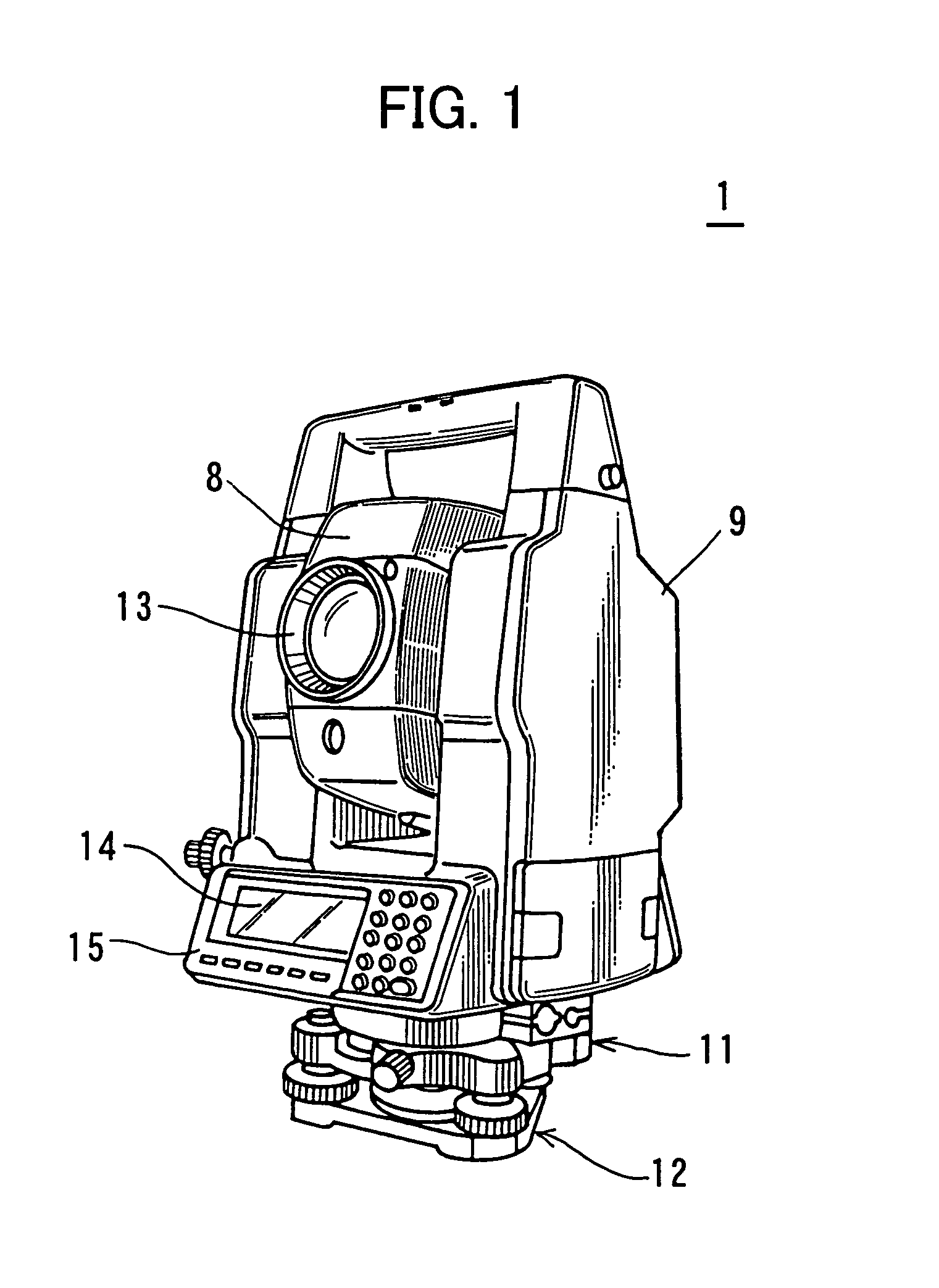
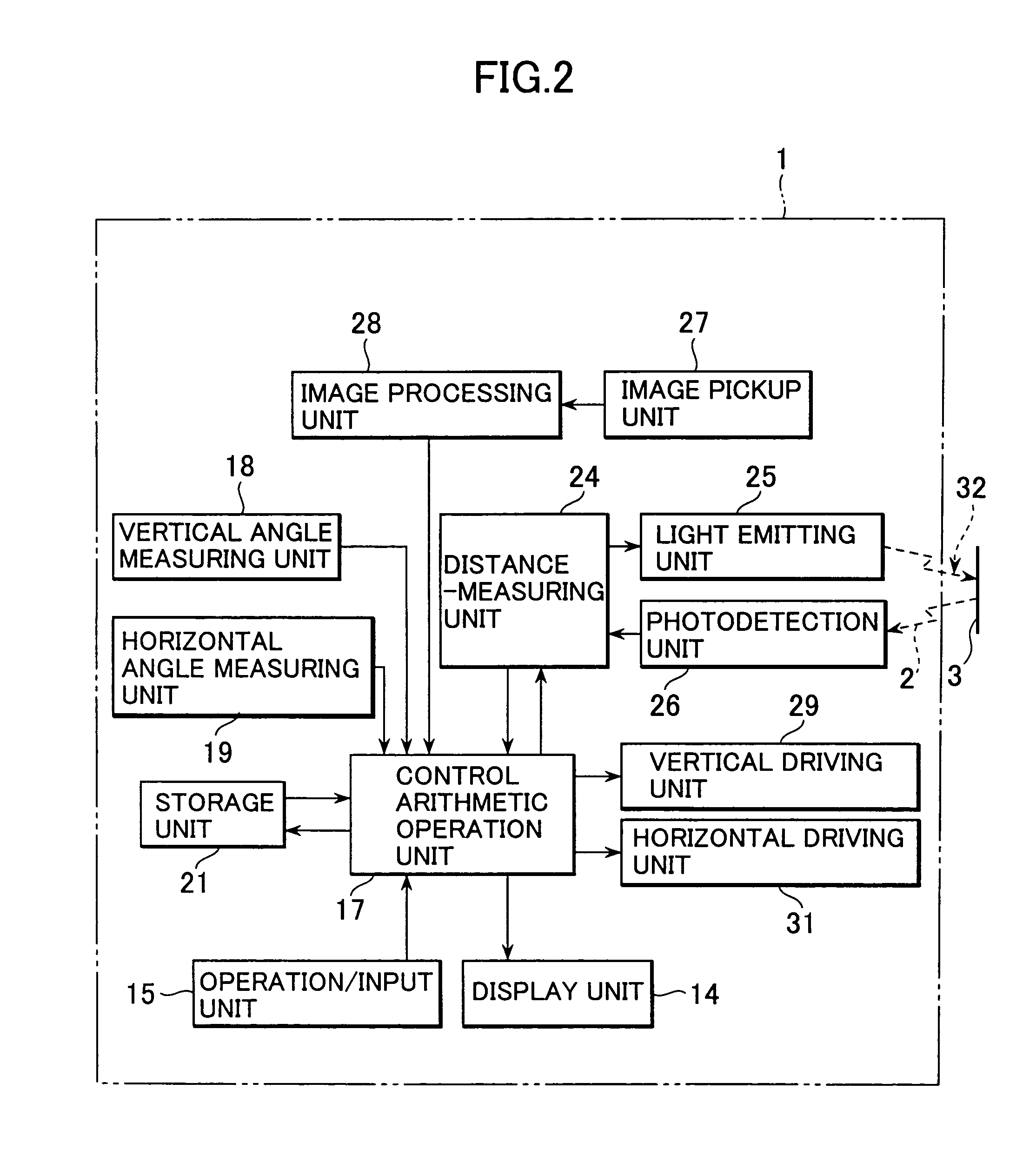
[0023]FIG. 1 represents an external appearance of a surveying instrument (total station) according to the present invention. In the figure, a surveying instrument 1 comprises an electronic theodolite for detecting angles (vertical angle and horizontal angle) and a light wave distance-measuring system.

[0024]The surveying instrument 1 primarily comprises a telescope unit 8, a frame unit 9 for rotatably supporting the telescope unit 8 in upward and downward direction, a base unit 11 for rotatably supporting the frame unit 9 to rotate in horizontal direction, and a leveling unit 12 for supporting the base unit 11. The leveling unit 12 can be mounted on a tripod or the like.

[0025]An optical system including an objective lens 13, an image pickup unit, etc. are incorporated in the telescope unit 8. The frame unit 9 comprises a display unit 14 and an operation / input unit 15.

[0...


PUM


Abstract

A surveying instrument, comprising an optical system for collimating a measuring point, a driving unit for performing scanning in a measurement range the optical system, a distance-measuring unit comprising a light wave distance measuring system, an image pickup unit for taking an image in the measurement range, an image processing unit for performing image processing to extract edges from the image picked up, and a control arithmetic operation unit for selecting a point near the edge as a measuring point on the image picked up and for controlling the distance-measuring unit to carry out surveying operation of the measuring point.

Description

BACKGROUND OF THE INVENTION[0001]The present invention relates to a surveying instrument of non-prism type for 3-dimensional measurement.[0002]When 3-dimensional data is to be surveyed on an object such as a building within a predetermined range, there have been disadvantages in the past in that much time was required and there was limitation in acquired amount of the surveying data because an operator must determine a measuring point and surveying operation must be carried out one point after another. By an automatic surveying instrument, in which surveying operation is automated, raster scanning is performed by measuring a predetermined range with fine pitch, and a vast amount of 3-dimensional surveying data can be collected more quickly than in the operation by the surveying operator. By putting together the vast amount of 3-dimensional data, 3-dimensional display can be achieved.[0003]In a conventional type automatic surveying instrument, a great number of measuring points are r...

Claims


Application Information

Patent Timeline
Patent Type & Authority Patents(United States)
IPC IPC(8): G06K9/00G06K9/40G01B11/24G01C15/00
CPCG01C15/002
Inventor OHTOMO, FUMIOOTANI, HITOSHIOMORI, MAKOTO
Owner KK TOPCON
Why Eureka
Try Eureka