Flight display system with enhanced temporal depiction of navigation information

a technology of flight display and enhanced temporal representation, which is applied in the field of enhanced temporal representation of navigation information in flight display, can solve the problem of no method for graphically displaying a type of “time window

Active Publication Date: 2010-07-27
ROCKWELL COLLINS INC
View PDF6 Cites 73 Cited by
  • Summary
  • Abstract
  • Description
  • Claims
  • Application Information

AI Technical Summary

Problems solved by technology

Currently, there is no method for graphically displaying a type of “Time Window” on the typical navigation map.

Method used


Image

  • Flight display system with enhanced temporal depiction of navigation information
  • Flight display system with enhanced temporal depiction of navigation information
  • Flight display system with enhanced temporal depiction of navigation information

Examples


Embodiment Construction

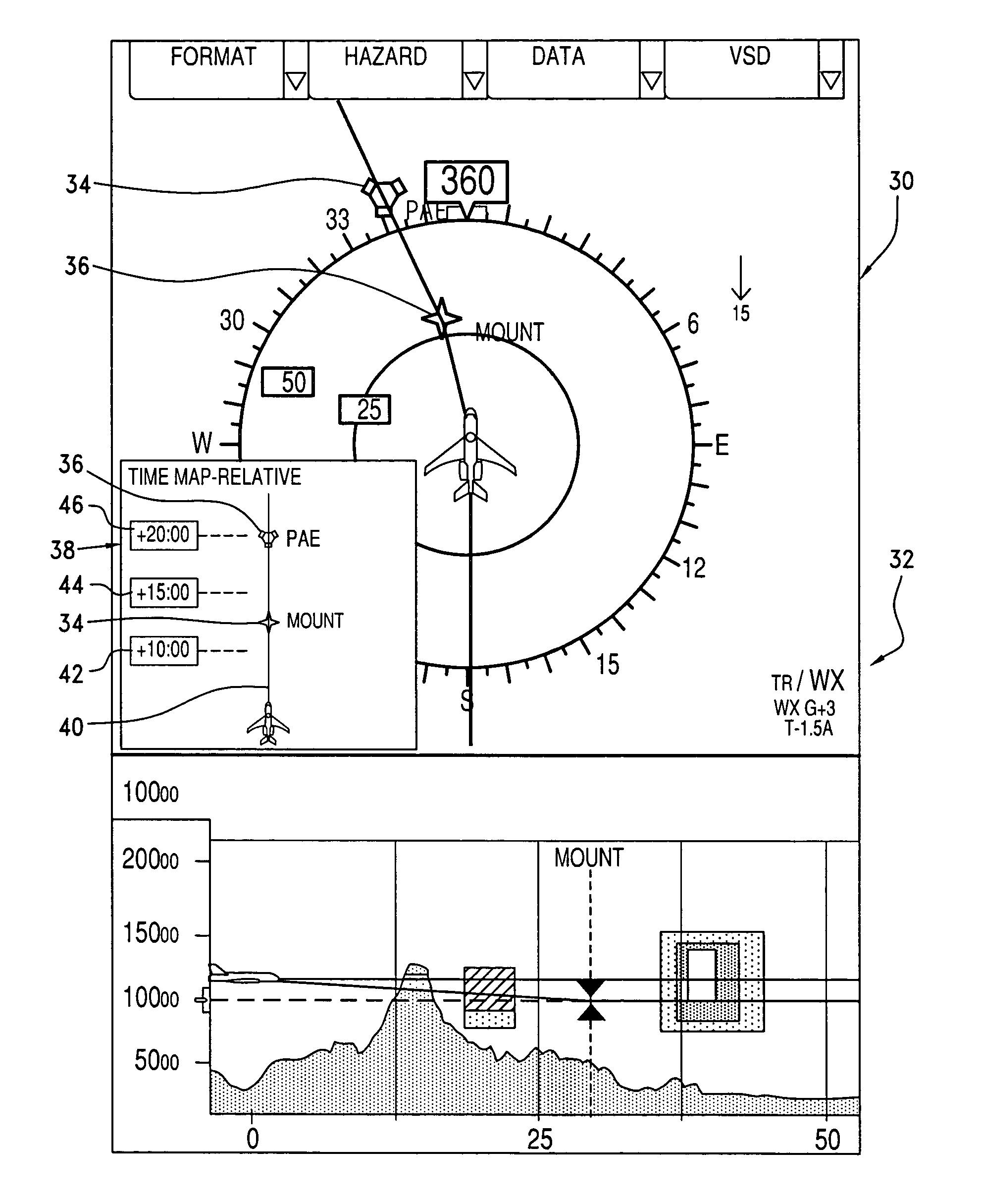
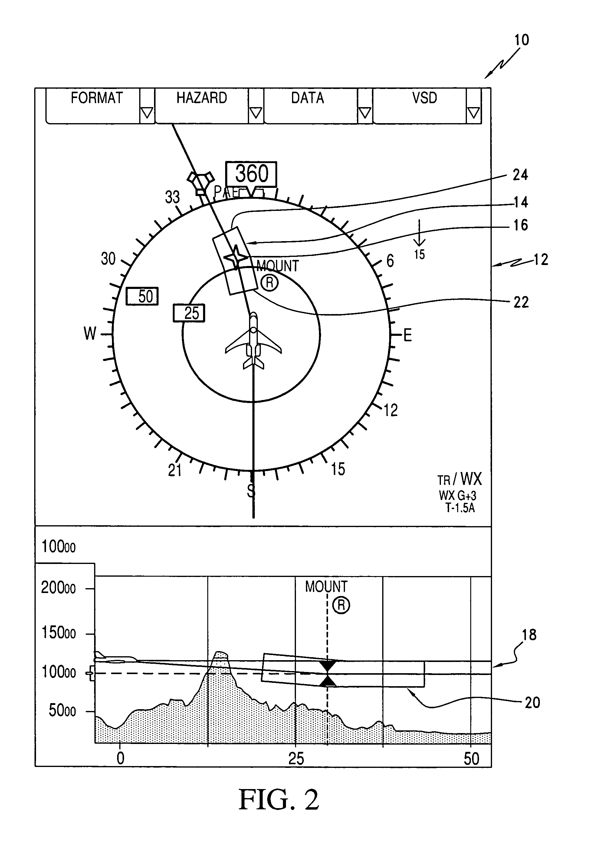
[0028]Referring now to FIG. 2 a flight display system, designated generally as 10, is illustrated in accordance with the principles of the present invention. In this figure, the flight display system 10 includes two navigation maps. The upper navigation map is a lateral map 12 that includes a two-dimensional box, designated generally as 14, representing a time window for a required time of arrival (RTA) waypoint 16. The lower navigation map is a vertical situation display 18. In this display 18 the time window is also depicted as a two-dimensional box 20.

[0029]Each time window i.e. spatial envelope, e.g. box 14, includes a proximal end 22 indicating a spatial location of the aircraft's position at the RTA using a defined lowest speed and a distal end 24 indicating a spatial location of the aircraft's position at the RTA using a defined highest speed. This defined lowest speed is typically the slowest cruise speed. However, it may represent other speeds such as the minimum flaps oper...


PUM


Abstract

In one aspect, the flight display system comprises a navigation map that includes a time window for a required time of arrival (RTA) waypoint. The time window has a proximal end indicating the aircraft's position at the RTA using a defined lowest speed and a distal end indicating the aircraft's position at the RTA using a defined highest speed. In another aspect, a pop-up time map displays flight plan waypoints mapped out along a time line adjacent to a plurality of time markers. The waypoint scrolls along the time line during flight. In another aspect, the flight display system includes a full format time map for displaying at least one flight plan waypoint mapped out along a time line adjacent to a plurality of time markers. In another broad aspect, a time/bearing map includes a plurality of concentric “range” rings corresponding to selected times in the future; a plurality of radially spaced bearing ticks positioned at selected locations about the concentric rings; and, a relative time ring presentable about a central axis of, and internal to, the concentric rings. The relative time ring represents a fixed increment in time. Selected waypoints are presentable at their relative bearing to the airplane and at their range (in time) from the airplane.

Description

BACKGROUND OF THE INVENTION[0001]1. Field of the Invention[0002]The present invention relates generally to aircraft instrumentation displays and more particularly to the enhancement in the display of an avionics flight display with enhanced temporal depiction of navigation information.[0003]2. Description of the Related Art[0004]Some Flight Management Systems (FMS) for aircraft provide a Required Time of Arrival (RTA) function, which can be associated with one or more waypoints. This type of function is necessary to enable 4-D navigation, which requires the airplane to pass over a given waypoint at a certain time. With today's navigation systems, a tolerance of 30 seconds is typically allowed at the RTA waypoint.[0005]Today, the pilot sets up the RTA for a waypoint by selecting an FMS Control Display Unit (CDU) page, as shown in the example below. FIG. 1 (Prior Art) shows a page that currently exists on the Smith's FMS (Boeing 737). When the RTA waypoint has been input, the FMS calc...

Claims


Application Information

Patent Timeline
Patent Type & Authority Patents(United States)
IPC IPC(8): G01C21/00
CPCG01C23/00
Inventor BARBER, SARAHSEAH, KIRSCHEN A.
Owner ROCKWELL COLLINS INC
Why Eureka
Try Eureka