Turbine airfoil cooling system with platform cooling channels with diffusion slots

a technology of diffusion slots and turbine airfoils, which is applied in the direction of liquid fuel engines, machines/engines, mechanical equipment, etc., can solve the problems of reducing the useful life of the turbine blade, the possibility of failure, and localized hot spots, so as to improve the overall platform cooling efficiency, reduce the consumption of cooling fluid, and reduce the temperature of the platform

Inactive Publication Date: 2010-08-03
SIEMENS ENERGY INC
View PDF19 Cites 25 Cited by
  • Summary
  • Abstract
  • Description
  • Claims
  • Application Information

AI Technical Summary

Benefits of technology

[0005]This invention is directed to a turbine airfoil cooling system for a turbine airfoil used in turbine engines. In particular, the turbine airfoil cooling system includes a plurality of internal cavities positioned between outer walls of the turbine airfoil. The cooling system may include a plurality of platform cooling channels positioned in a platform of the turbine airfoil. In particular, the platform may include one or more suction side platform cooling channels positioned proximate to a suction side of the turbine airfoil and one or more pressure side platform cooling channels positioned proximate to a pressure side of the turbine airfoil. The pressure side platform cooling channels may include one or more diffusion slots extending through a side edge of the platform to cool an adjacent turbine airfoil via film cooling. Such a configuration of cooling fluids creates a double use of cooling fluids that improves the overall platform cooling efficiency, reduces the platform metal temperature and reduces cooling fluid consumption.
[0010]The cooling fluids may also flow through the pressure side platform cooling channel where the temperature of the local hot spot is reduced. The cooling fluids may flow into the diffusion slots where the velocity of the cooling fluids is reduced. The cooling fluids may then be released from the diffusion slots of the pressure side platform cooling channel through the exhaust openings. The cooling fluids may form a layer of film cooling air immediately proximate to the outer surface of the platform. This configuration of the cooling system cools the platform with both external film cooling and internal convection. This double use of cooling fluids improves the overall platform cooling efficiency, reduces the platform metal temperature and reduces cooling fluid consumption.
[0011]An advantage of this invention is that the diffusion slots of the pressure side platform cooling channels, together with the suction side platform cooling channels, create a double use of cooling fluids that cooling internal aspects of the platform with convective cooling and an external surface of the platform with convective film cooling. Such use of the cooling fluids increases the efficiency of the cooling fluids and reduces the temperature gradient of the platform across its width.

Problems solved by technology

In addition, turbine blades often contain cooling systems for prolonging the life of the blades and reducing the likelihood of failure as a result of excessive temperatures.
However, centrifugal forces and air flow at boundary layers often prevent some areas of the turbine blade from being adequately cooled, which results in the formation of localized hot spots.
Localized hot spots, depending on their location, can reduce the useful life of a turbine blade and can damage a turbine blade to an extent necessitating replacement of the blade.
While these cooling channels reduce the temperature of portions of the platform, there are several drawbacks.
For instance, the use of film cooling for the entire blade platform requires that the supply pressure of the cooling air at the blade dead rim cavity be higher than the peak blade platform external gas side pressure, which induces a high leakage flow around the blade attachment region and impacts performance.
In addition, conventional designs often include cooling channels extending from the platform edge into the cooling cavities of the airfoil, which causes unacceptable stress levels at the internal airfoil and platform cooling cavities, thereby yielding a low blade life.
Furthermore, conventional platform cooling systems often create localized hot spots proximate to the pressure side of the airfoil and proximate to the suction side, further reducing the blade life.

Method used


Image

  • Turbine airfoil cooling system with platform cooling channels with diffusion slots
  • Turbine airfoil cooling system with platform cooling channels with diffusion slots
  • Turbine airfoil cooling system with platform cooling channels with diffusion slots

Examples


Embodiment Construction

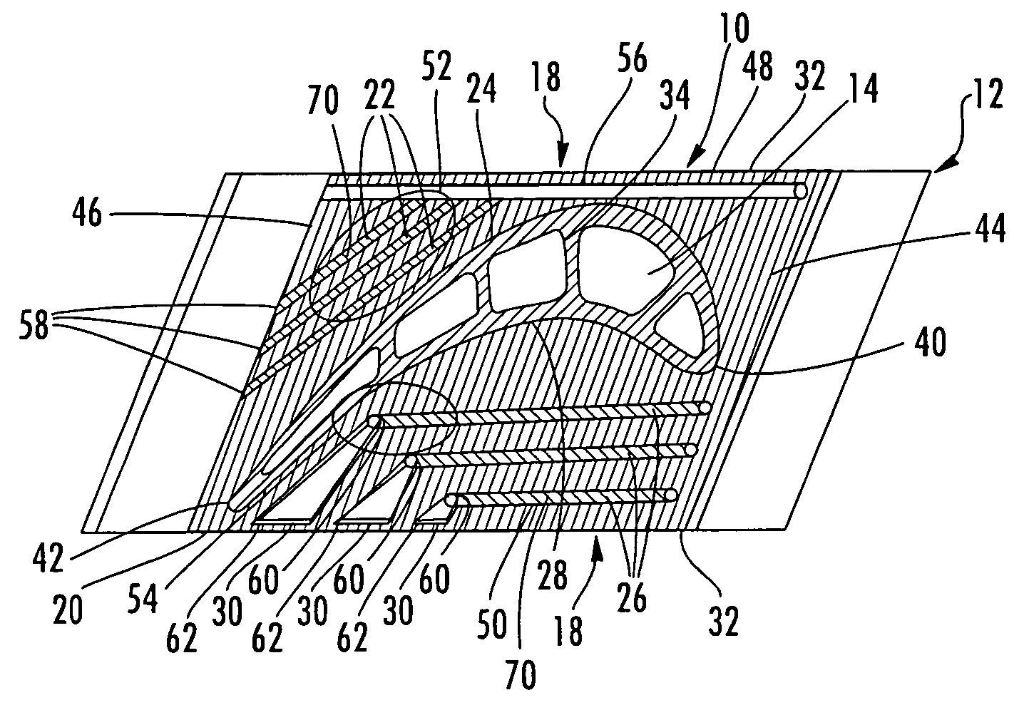
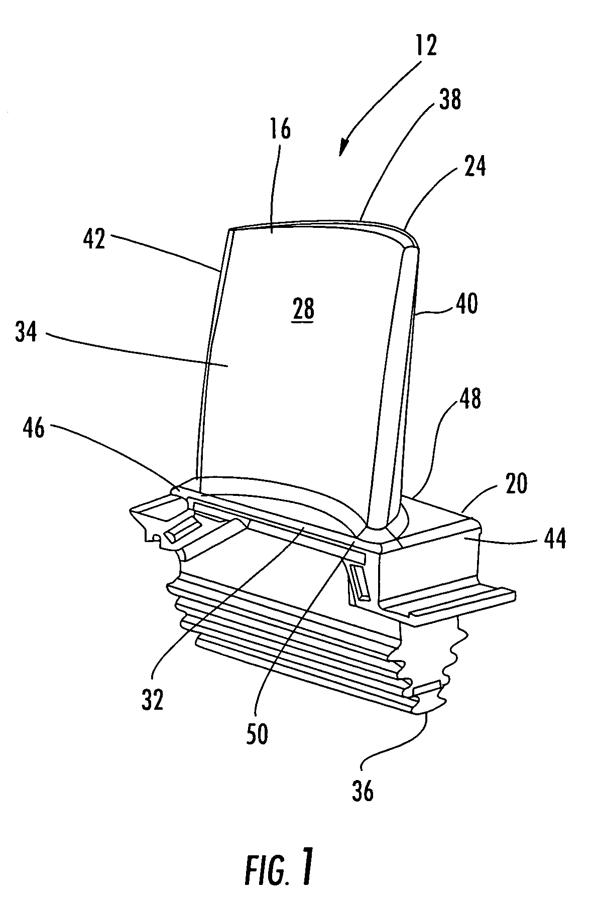
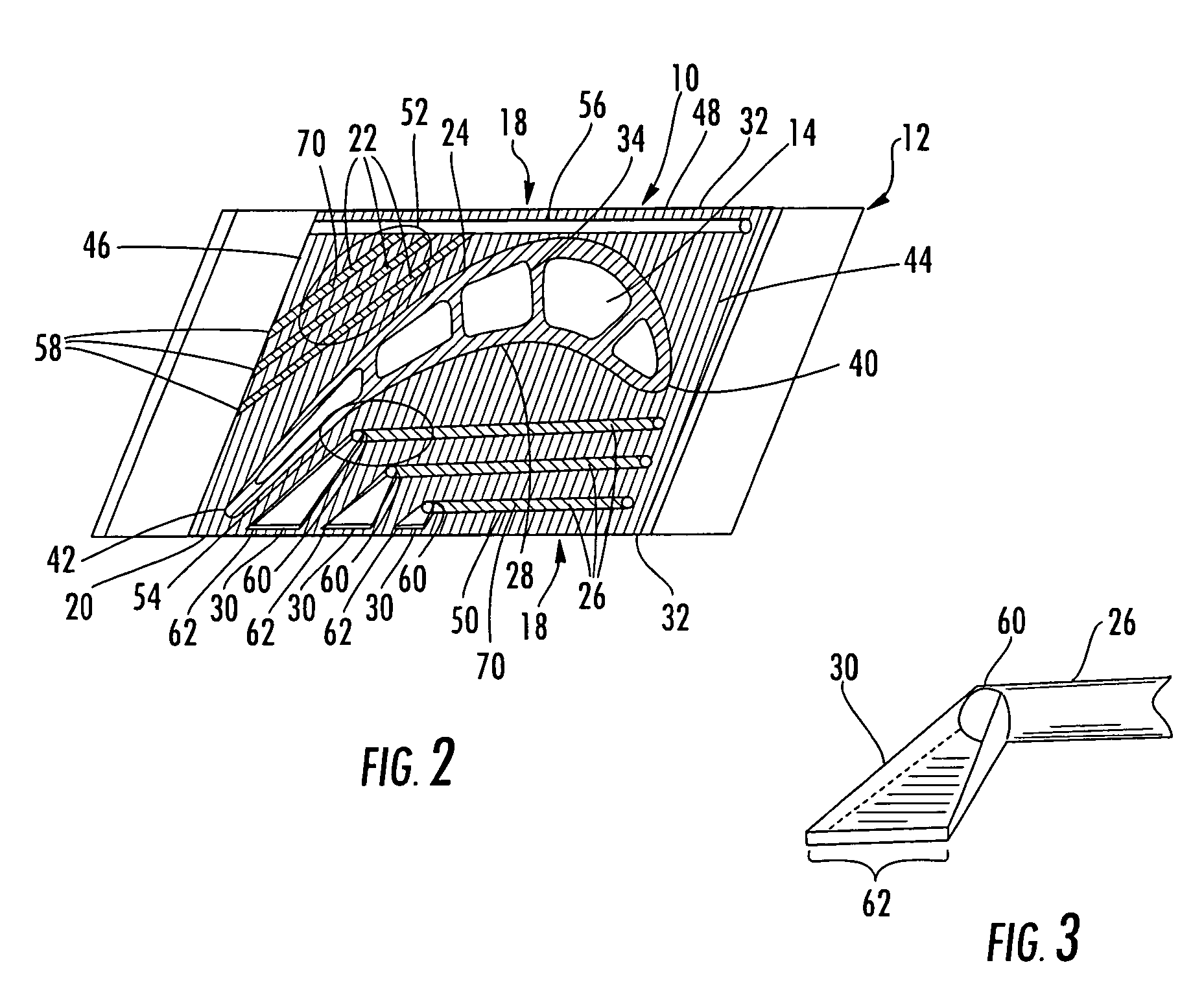
[0018]As shown in FIGS. 1-4, this invention is directed to a turbine airfoil cooling system 10 for a turbine airfoil 12 used in turbine engines. In particular, the turbine airfoil cooling system 10 includes a plurality of internal cavities 14, as shown in FIG. 2, positioned between outer walls 16 of the turbine airfoil 12. The cooling system 10 may include a plurality of platform cooling channels 18 positioned in a platform 20 of the turbine airfoil 12. In particular, the platform 20 may include one or more suction side platform cooling channels 22 positioned proximate to a suction side 24 of the turbine airfoil 12 and one or more pressure side platform cooling channels 26 positioned proximate to a pressure side 28 of the turbine airfoil 12. The pressure side platform cooling channels 26 may include one or more diffusion slots 30 extending through a side edge 32 of the platform 20 to cool an adjacent turbine airfoil via film cooling.

[0019]As shown in FIG. 1, the turbine airfoil 12 m...


PUM


Abstract

A cooling system for a turbine airfoil of a turbine engine having suction side platform cooling channels and pressure side platform cooling channels for cooling hot spots in a platform attached to a turbine blade. The cooling system may include one or more pressure side platform cooling chambers having a diffusion slot for cooling downstream platforms on the suction side of the turbine blade. The diffusion slots reduce the velocity of the cooling fluids released from the platform to increase the capacity of the film cooling of downstream platforms.

Description

FIELD OF THE INVENTION[0001]This invention is directed generally to turbine airfoils, and more particularly to cooling systems in hollow turbine airfoils.BACKGROUND[0002]Typically, gas turbine engines include a compressor for compressing air, a combustor for mixing the compressed air with fuel and igniting the mixture, and a turbine blade assembly for producing power. Combustors often operate at high temperatures that may exceed 2,500 degrees Fahrenheit. Typical turbine combustor configurations expose turbine blade assemblies to these high temperatures. As a result, turbine blades must be made of materials capable of withstanding such high temperatures. In addition, turbine blades often contain cooling systems for prolonging the life of the blades and reducing the likelihood of failure as a result of excessive temperatures.[0003]Typically, turbine blades are formed from a root portion having a platform at one end and an elongated portion forming a blade that extends outwardly from t...

Claims


Application Information

Patent Timeline
Patent Type & Authority Patents(United States)
IPC IPC(8): F01D5/18
CPCF01D5/187F05D2260/202F05D2250/324F05D2240/81
Inventor LIANG, GEORGE
Owner SIEMENS ENERGY INC
Why Eureka
Try Eureka