
Suture anchor and approximating device

a technology of approximating device and suture anchor, which is applied in the field of suture anchor and minimally invasive methods, can solve the problems of sacrificing the strength of tissue anchoring, affecting the stability of the suture anchor, so as to improve the anchoring strength within the tissu

Inactive Publication Date: 2010-08-03
TELEFLEX LIFE SCI LTD
View PDF16 Cites 54 Cited by
  • Summary
  • Abstract
  • Description
  • Claims
  • Application Information

AI Technical Summary

Benefits of technology

The invention is a suture anchor that can be used to fasten tissue together. It is designed to be easily inserted into tissue and can be attached to a needle for easy manipulation. The anchor has a curved shape that allows for secure anchoring within tissue without the need for a separate needle. The anchor can be used in various procedures such as urology, gynecology, and uterus positioning. It is designed to improve anchoring strength within tissue and can be used in multiple anchoring or tissue repair procedures. The anchor can be easily detached from the needle and resiliently straightened within tissue. It can also be used in combination with other anchors to close tissue at a specific depth. The anchor is designed to resume its original shape within tissue, increasing the distance between the openings for the suture and resisting pullout. The invention also includes a suture delivery system with a needle and a platform for positioning the anchor. The needle can be a rigid or flexible material, and the platform can be used to deliver multiple anchors in series into tissue. The invention improves the ease and effectiveness of tissue fastening and repair.

Problems solved by technology

Since the anchors reside within the lumen of the delivery device, the size of the needles or tubular members is correspondingly larger, making tissue penetration more difficult and traumatic.
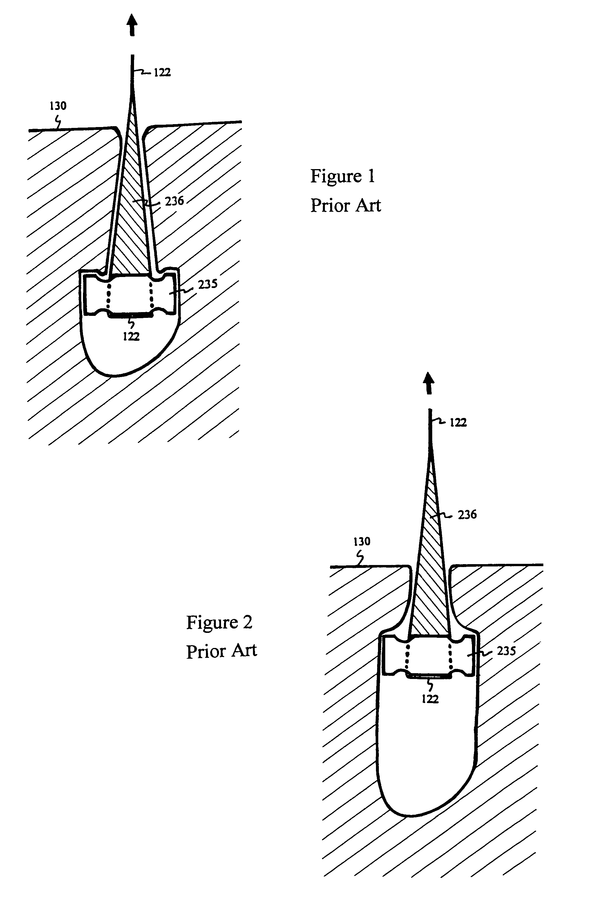
While the widely spaced suture 122 provides favorable leverage for rapid rotation, it appears to sacrifice the strength of tissue anchoring.
Unfortunately, most tissue within the body adheres to adjacent tissue with no clear separation, space or cavity.
Therefore, full-thickness anchor pivoting to fasten or proximate two tissues has limited use.

Method used


Image

  • Suture anchor and approximating device
  • Suture anchor and approximating device
  • Suture anchor and approximating device

Examples


Embodiment Construction

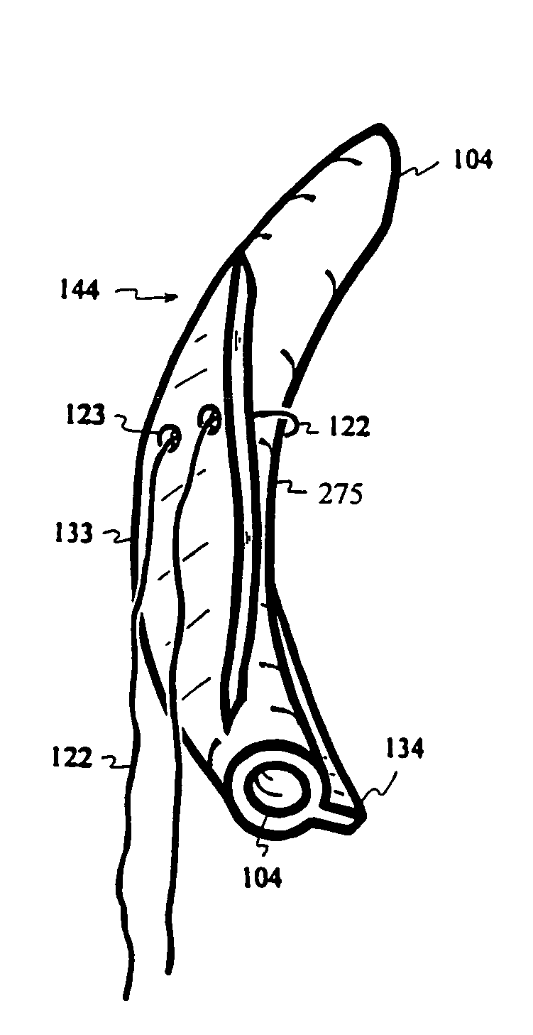
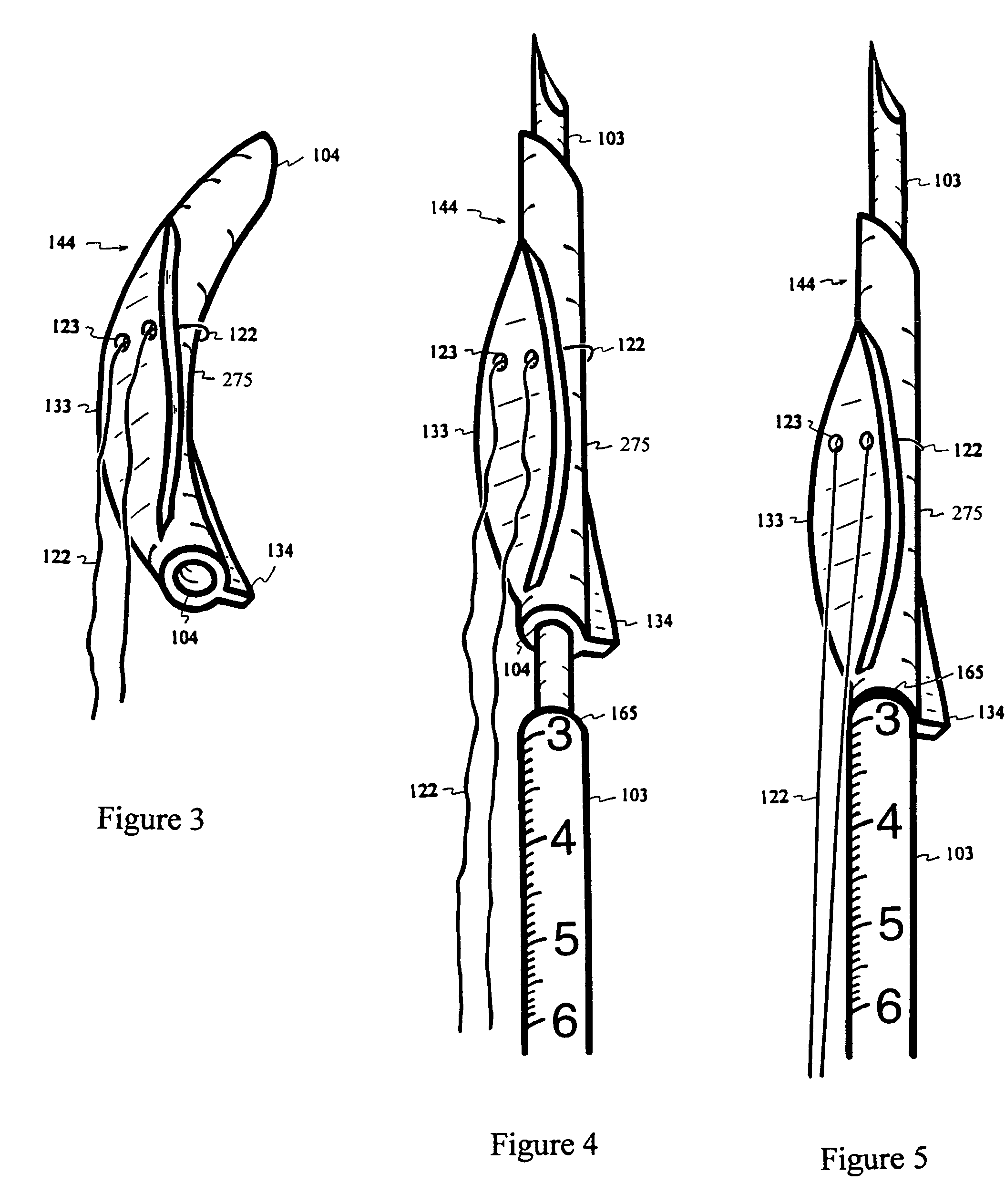
[0191]A curved anchor 144 is made with elastic material containing a longitudinal lumen or passage 104, a fin 134 at or near the proximal end, and a relatively flat platform 133 on the convex side of the curvature with two openings 123 for a suture 122, as shown in FIG. 3. Through the openings 123 on the platform 133, the suture 122 is looped around the concave side of the curved anchor 144 for tension distribution. FIG. 4 depicts a relatively rigid trocar or needle 103 inserted through the lumen 104 to resiliently straighten the elastic anchor 144. The needle 103 is marked with measuring units, visible under endoscope, to indicate depth of needle 103 penetration into tissue. The distal portion of the needle 103 is sized and configured to fit into the lumen 104 of the anchor 144. To prevent the anchor 144 from sliding up the needle 103 during tissue penetration, the cross-sectional diameter of the needle 103 is not uniform. A step 165 on the needle 103, as shown in FIGS. 4 and 5, bl...


PUM


Abstract

An elastically curved suture anchor is resiliently straightened and delivered into tissue by a needle. When the needle is withdrawn, resumption of the curvature provides leverage for anchor rotation as the attached suture is pulled to fasten the anchor within the tissue. A fin at the proximal end of the anchor further increases the rotational leverage and expedites anchor fastening. When two or more anchors with connecting suture are delivered in series on a needle, the tension of the suture helps to draw the anchors together and approximates the pierced tissue.

Description

CROSS-REFERENCES TO OTHER APPLICATIONS[0001]This application is a continuation of PCT Application serial number PCT / US02 / 41399 filed Dec. 24, 2002, which claimed priority of U.S. Application 60 / 364,947 filed on Mar. 14, 2002.FIELD OF INVENTION[0002]This invention relates to suture anchors and minimally invasive methods for delivering and fastening suture within tissue.BACKGROUND[0003]Suture anchors have been developed for anchoring sutures in endoscopic or arthroscopic surgery through single sided access. Most prior art suture anchors are delivered from a lumen of a needle or a tubular device. Prior art include U.S. Pat. No. 4,235,238 by H. Ogiu et al., issued on Nov. 25, 1980, U.S. Pat. No. 4,741,330 by J. Hayhurst, issued on May 3, 1988, U.S. Pat. No. 4,669,473 by W. Richards et al., issued on Jun. 2, 1987, U.S. Pat. No. 5,800,445 by K. Ratcliff et al., issued on Sep. 1, 1998; U.S. Pat. No. 5,041,129 by J. Hayhurst et al., issued on Aug. 20, 1991, U.S. Pat. No. 5,845,645 by P. Bon...

Claims


Application Information

Patent Timeline
Patent Type & Authority Patents(United States)
IPC IPC(8): A61B17/04A61B17/00A61B19/00
CPCA61B17/0401A61B17/0467A61B2017/00805A61B2017/0409A61B2017/0412A61B2017/0414A61B2019/462A61B2017/0445A61B2017/0446A61B2017/045A61B2017/0458A61B2017/0464A61B2017/0496A61B2017/0437A61B2090/062
Inventor YEUNG, JEFFREY ERICYEUNG, TERESA T.
Owner TELEFLEX LIFE SCI LTD
Learn More