Speaker system with oscillation detection unit

a technology of oscillation detection and speaker system, which is applied in the field of speaker system, can solve the problems of reducing the degree of affecting the accuracy of detecting the displacement of the oscillation system, and the weight distribution imbalance of the voice coil unit, etc., and achieves the effects of high cost, superior heat resistance, and heavy weigh

Inactive Publication Date: 2010-08-03
ROLAND CORP
View PDF10 Cites 54 Cited by
  • Summary
  • Abstract
  • Description
  • Claims
  • Application Information

AI Technical Summary

Benefits of technology

[0022]In addition, even though the first component part is attached to the voice coil unit, since the first component part and the second component part are positioned along the center axis of the voice coil unit, the imbalance in the weight distribution of the voice coil unit with respect to the center axis of the voice coil unit is minimized. Therefore, the occurrence of rolling and the degradation of sound quality is reduced and it is possible to detect the piston motion, the original oscillating action of the voice coil unit, with a relatively high degree of accuracy.
[0034]In accordance with the speaker system of an eighth preferred embodiment, the reflecting member is made of a resin that has been molded in a single unit with the linking members and is configured with an aluminum reflecting plate mounted on at least the portion that faces the light sensor unit. Accordingly, in addition to the advantages of the speaker system of the fifth embodiment, it is possible to use a resin material that cannot be plated with a mirror surface but has high heat resistance or a resin material with which the stability of the mirror surface plating is low.

Problems solved by technology

However, there are problems associated with affixing the reflecting plate to the inner surface of the dust cap, as disclosed in the first patent reference above.
These effects degrade the degree of accuracy of detecting the displacement of the oscillation system.
There are also problems in a system where, as disclosed in the second patent reference above, the reflecting plate is affixed to the lower edge portion of the voice coil unit.
One problem is that the reflecting plate causes a weight distribution imbalance of the voice coil unit with respect to a center axis of the voice coil.
With an imbalance, a rolling oscillation that involves an inclination from the center axis of the voice coil unit is produced.
Therefore, the rolling oscillation caused by the weight imbalance degrades the accuracy of the detection of the original oscillation action of the voice coil unit.
In addition, because of the rolling oscillation, ideal oscillation is not possible and sound quality becomes relatively degraded as a result.
A second problem is that the voice coil is a source of heat generation.
However, since metal materials are relatively heavy, the use of metal for the reflecting member increases the weight of the voice coil unit.
This added weight adversely affects the original oscillation action of the voice coil unit.
However, when heat resistance properties are taken into consideration, the resin materials that can be used are limited to resins with superior heat resistant properties (for example, engineering plastic).
The resins with superior heat resistant properties are relatively high in cost, which increases the manufacturing cost of the overall system.
A third problem is that, because of the limitations in the size of the system, the light sensor is disposed directly below the reflecting member and must be arranged in the vicinity of the voice coil unit.
This creates a problem because the characteristics of the light sensor may change or, depending on the circumstances, the light sensor may be destroyed due to the heat generated by the voice coil.

Method used


Image

  • Speaker system with oscillation detection unit
  • Speaker system with oscillation detection unit
  • Speaker system with oscillation detection unit

Examples


Embodiment Construction

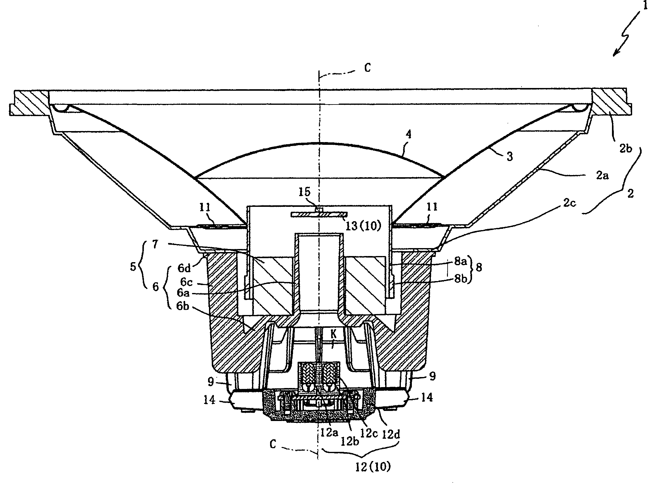
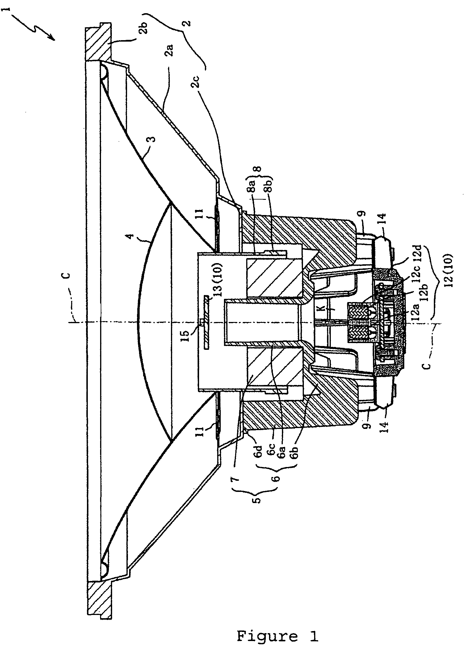
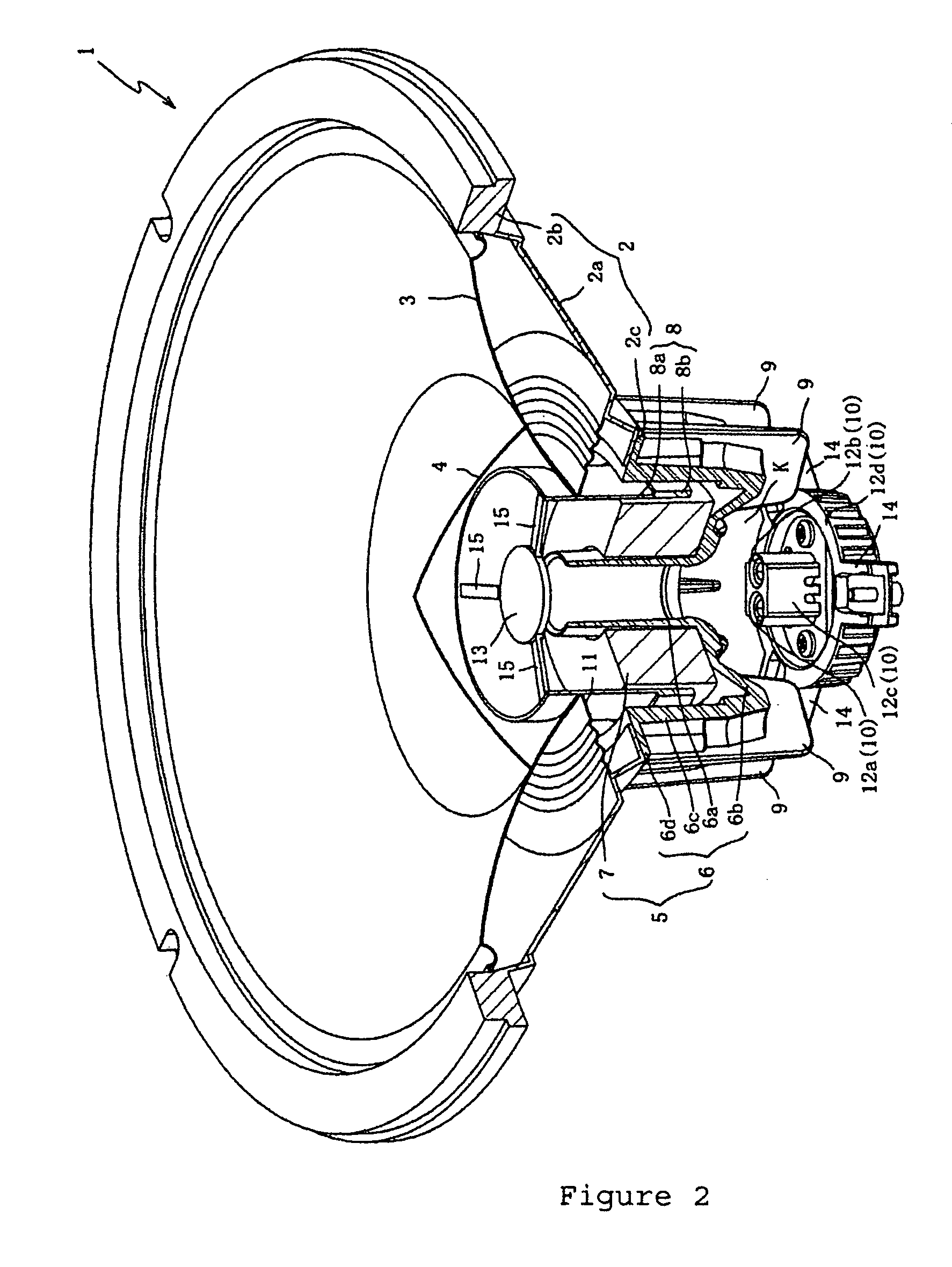
[0038]An explanation will be given below regarding preferred embodiments of the present invention while referring to the attached drawings. First, an explanation will be given regarding a first preferred embodiment of a speaker system of the present invention. FIG. 1 is a cross-section drawing of the speaker system 1 of the first preferred embodiment. FIG. 2 is an oblique external view drawing of the speaker system 1 of the first preferred embodiment and shows a portion of the speaker system 1 in cross-section.

[0039]The speaker system 1 is a system capable of detecting the oscillations of the voice coil unit 8 with a high degree of accuracy to produce a high fidelity reproduction. As is shown in FIG. 1, the speaker system 1 primarily comprises a frame 2, a cone 3, a dust cap 4, a magnetic circuit 5, a voice coil unit 8, heat radiating fins 9, and a detection unit 10.

[0040]The frame 2 supports the cone 3 and the like. The frame 2 comprises a main body frame 2a, a first flange 2b, and...


PUM


Abstract

A speaker system comprising a magnetic circuit, a cylindrical shaped voice coil unit generating oscillation in the magnetic circuit, an oscillating plate extending in a circular conical shape from a outer peripheral surface of the voice coil unit, a dust cap connecting to the oscillating plate covering an open face of the voice coil unit on a side surrounded by the oscillating plate, a plurality of linking members connecting to the voice coil unit, and a detection unit. The link members extend toward a center axis of the voice coil unit. The detecting unit further comprises a first component part fastened to the linking members and positioned at the center axis of the voice coil unit closer to the voice coil unit side than the dust cap, and a second component part positioned facing the first component part and is independent of the voice coil unit such that the second component part is held between the first component part and the dust cap. The detecting unit optically detects the oscillations of the voice coil unit by means of a light that courses between the previously mentioned first component part and the second component part.

Description

CROSS-REFERENCE TO RELATED PATENT APPLICATIONS[0001]The present invention relates to Japanese patent applications No. 2005-272354 (filed on Sep. 20, 2005), which was assigned to the assignees of the present invention and is incorporated herein by reference in its entirety and from which priority is claimed for the present invention.BACKGROUND OF THE INVENTION[0002]The present invention relates to a speaker system that detects the oscillation of the voice coil unit with a high degree of accuracy, thus enabling a high fidelity reproduction by the speaker system.[0003]For some time, a detection unit that detects the oscillation displacement of an oscillation system that comprises a voice coil unit, an oscillation plate, and a dust cap has been installed in speaker systems. The detection results by the detection unit are employed in generating a negative feedback through acquiring the difference between the detected oscillation displacement and the input signal. Thus, by compensating th...

Claims


Application Information

Patent Timeline
Patent Type & Authority Patents(United States)
IPC IPC(8): H04R25/00
CPCH04R9/02H04R9/06
Inventor TAKAGI, MASAYUKITAKATA, KOSUKEIKEGAMI, YOSHIHIRO
Owner ROLAND CORP
Why Eureka
Try Eureka