Head rest device

a head rest and head technology, applied in the direction of chairs, pedestrian/occupant safety arrangements, vehicular safety arrangements, etc., can solve the problems of limited arrangement of parts and parasitic capacity of wiring itself, and achieve the effect of reducing the parasitic capacity generated in wiring, stably performing detection, and reducing the characteristic of wire arranging

Inactive Publication Date: 2010-08-10
AISIN SEIKI KK +2
View PDF23 Cites 22 Cited by
  • Summary
  • Abstract
  • Description
  • Claims
  • Application Information

AI Technical Summary

Benefits of technology

[0008]If the structure of the wiring itself is electromagnetically shielded, for example, a coaxial cable or the like, it is possible to reduce the parasitic capacity generated in the wiring, and it is possible to stably perform detection. However, since such a wiring lacks a mechanical strength, and a wire arranging characteristic is lowered by an enlargement of a diameter of the wiring, an arrangement of the parts is limited.
[0009]Accordingly, it is an objective of the present invention is to provide a head rest device which improves the reliability of detection of a head on the basis of a change in a capacitance without complicating a wiring structure.
[0011]In accordance with the structure described above, since the driving device, the control circuit, the sensor electrode, and the capacitance detecting circuit are mounted to the head rest rear portion or the head rest front portion, it is possible to shorten the wiring between the driving device and the control circuit, and the wiring between the sensor electrode and the capacitance detecting circuit, in comparison with the case that both circuits are arranged outside the head rest device. Accordingly, it is possible to suppress a voltage drop between the members, and it is possible to suppress a parasitic capacity generated by the wirings that are provided long in parallel. Further, since it is possible to shorten the wiring between the sensor electrode and the capacitance detecting circuit, it is possible to suppress a parasitic capacity generated in the wiring itself, and a parasitic capacity generated between the wiring and the peripheral conductive material. Accordingly, it is possible to stably detect the capacitance changed on the basis of the approach of the head without complicating the wiring structure, and it is possible to improve the reliability of head detection.

Problems solved by technology

However, in this case, a parasitic capacity of a wiring itself may be generated between the sensor electrode and a circuit detecting the capacitance of the sensor electrode.
However, since such a wiring lacks a mechanical strength, and a wire arranging characteristic is lowered by an enlargement of a diameter of the wiring, an arrangement of the parts is limited.

Method used


Image

  • Head rest device
  • Head rest device
  • Head rest device

Examples


Embodiment Construction

[0027]A description will be given below of an embodiment obtained by embodying the present invention with reference to the accompanying drawings.

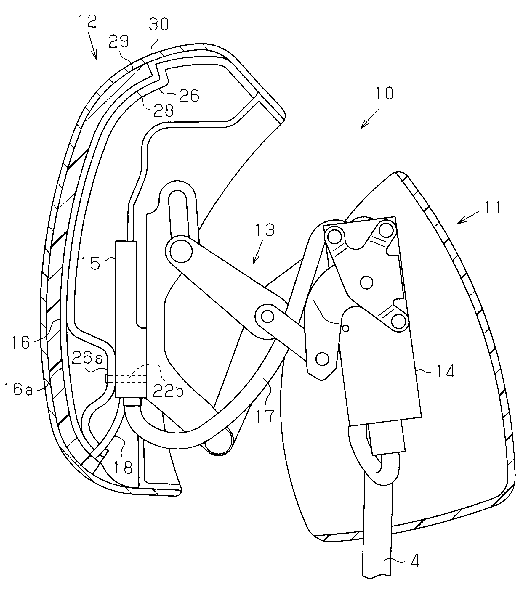
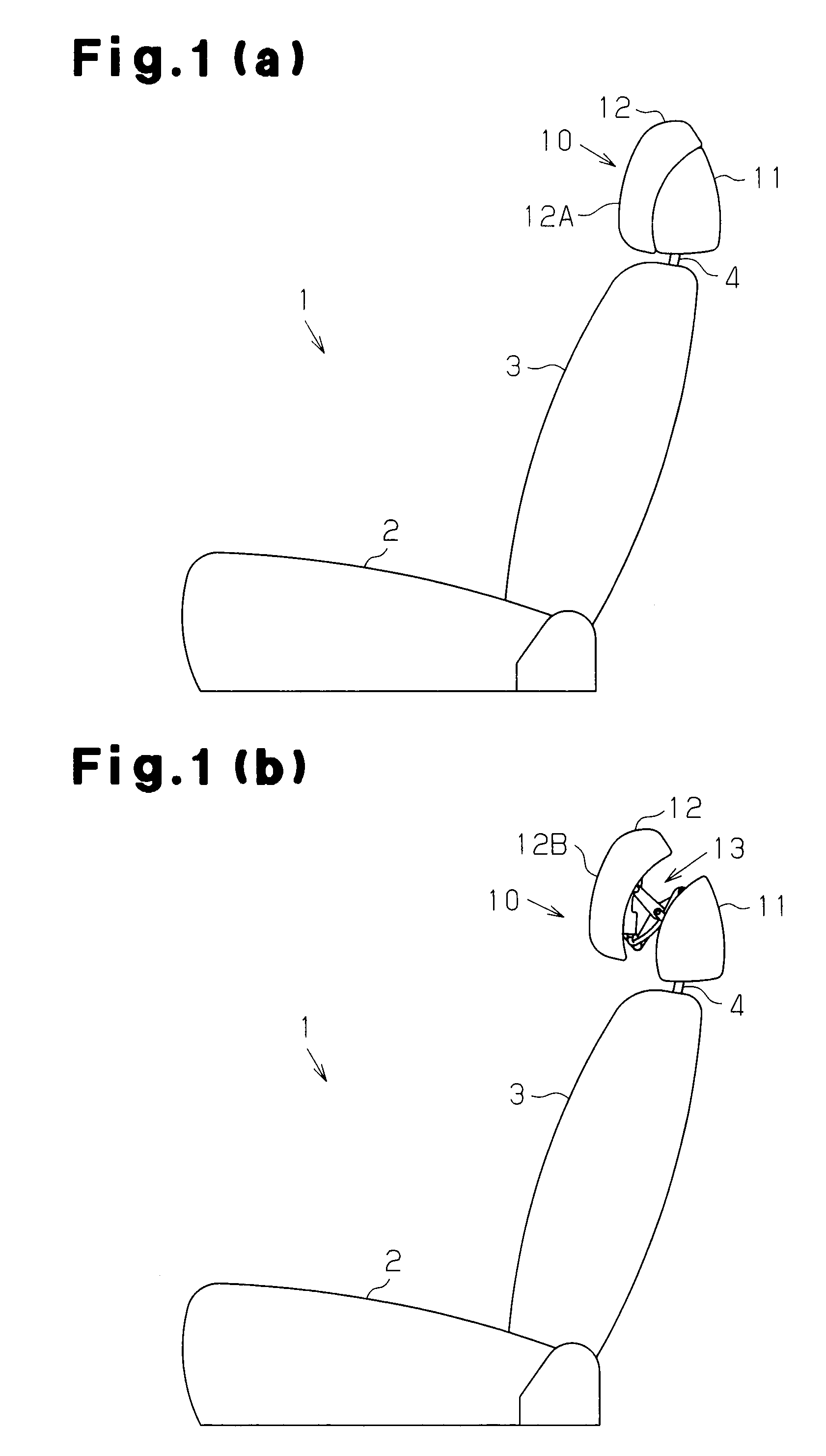
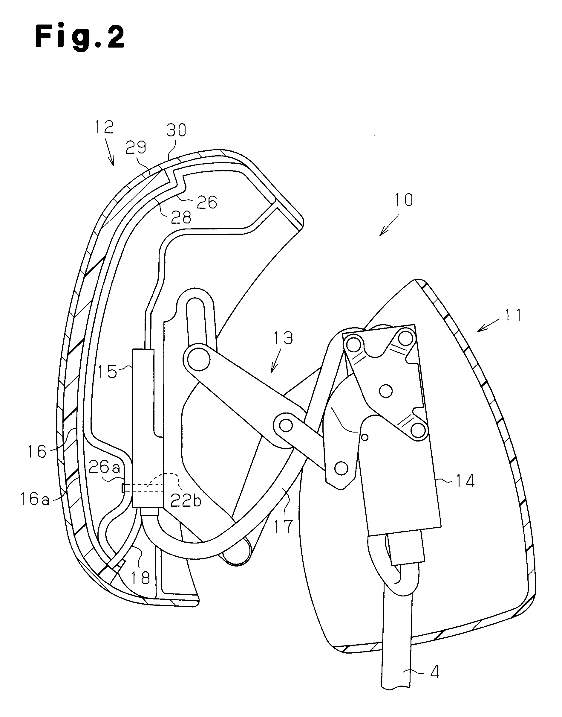
[0028]As shown in FIGS. 1(a) and 1(b), a vehicle seat 1, which is a front passenger seat of a vehicle such as an automobile is provided with a seat 2, a seat back 3 supported to the seat 2 so as to be tiltable, and a head rest device 10 provided in an upper end portion of the seat back 3.

[0029]The head rest device 10 is provided with a head rest rear portion 11 configured to be supported to a head rest stay 4 provided in an upper end portion of the seat back 3, and a head rest front portion 12 which is movable with respect to the head rest rear portion 11. Further, the head rest rear portion 11 and the head rest front portion 12 are coupled by an extensible mechanism 13. The head rest front portion 12 is movable forward and backward between a fully-closed position 12A coming close to the head rest rear portion 11 as shown in FIG. 1(a), and ...


PUM


Abstract

A head rest device that improves reliability of detecting a head on the basis of a change in capacitance without complicating a wiring structure. A head rest device is provided with a head rest rear portion configured to be supported to a seat back, and a head rest front portion freely moving forward and backward between a fully-closed position coming close to the head rest rear portion and a fully-open position separated from the head rest rear portion. The head rest front portion is moved by an actuator. The head rest front portion has a sensor electrode structured such that its capacitance is changed as a head of an occupant approaches, and an ECU controlling the actuator so as to move the head rest front portion and detecting the approach of the head of the occupant on the basis of a change of the capacitance of the sensor electrode thereon.

Description

FIELD OF THE INVENTION[0001]The present invention relates to a head rest device provided in a vehicle seat of an automobile or the like.BACKGROUND OF THE INVENTION[0002]If an impact is applied to a vehicle from a rear side in a state in which an occupant of the vehicle is not leaning against an upper body on a seat back, a head of the occupant rapidly moves to a head rest in accordance with a rapid movement of the upper body of the occupant to the seat back. At this time, a difference is generated between a moving amount of the upper body and a moving amount of the head of the occupant, and the head of the occupant moves rearward more largely than the upper body. Thereafter, the upper body of the occupant is largely oscillated forward on the basis of a reaction of the impact force. However, a load is applied to a neck region of the occupant on the basis of the difference of the moving amounts at this time.[0003]Thus, conventionally, for example, as disclosed in Patent Documents 1 an...

Claims


Application Information

Patent Timeline
Patent Type & Authority Patents(United States)
IPC IPC(8): A47C7/38B60N2/42B60N2/48B60R21/015
CPCB60N2/002B60N2/0244B60N2/4861B60N2/4885B60N2002/0268B60N2/888B60N2/862B60N2/0268
Inventor HIROTA, KOICHIITO, KOJIIYODA, MOTOMIOKAWA, TATSUHIROAKAIKE, FUMITOSHINISHIMURA, SEIYA
Owner AISIN SEIKI KK
Why Eureka
Try Eureka