Cassette-based power meter

a power meter and cassette technology, applied in the field of cassette-based power meter, can solve the problems of limiting the ability of users to transfer the power meter between bicycles, consuming a large amount of time, and cost prohibitive to outfit each bicycle with a power meter, and achieve the effect of cost-effectiveness

Active Publication Date: 2010-08-17
SRAM CORPORATION
View PDF53 Cites 104 Cited by
  • Summary
  • Abstract
  • Description
  • Claims
  • Application Information

AI Technical Summary

Benefits of technology

[0008]It is therefore an object of the present invention to provide a torque sensing device that is selectively interchangeable from bike-to-bike and / or wheel-to-wheel. It is yet another object of the present invention to provide a device powered by user operation of a pedal assembly that includes a torque sensing device that is relatively lightweight. It is yet another object of the present invention to provide a cost effective torque sensing system.

Problems solved by technology

One of the drawbacks of conventional hub-based power meters is that it is difficult and time consuming to remove and install the torque sensing components, thereby limiting a user's ability to transfer the power meter between bicycles.
As it is common for bicyclists to utilize different types of bicycles for different types of races, events, or training environments, a great deal of time may be consumed by having to disassemble the wheel structure of one wheel such that the hub assembly incorporating the torque sensor may be used with another bicycle.
Further, it can be cost-prohibitive to outfit each bicycle with a power meter when only one bicycle is being used at a time.
In addition, it is difficult for a manufacturer of a hub-based power meter to provide a power meter that can be used with all or a majority of the various rear wheel configurations that are available.

Method used


Image

  • Cassette-based power meter
  • Cassette-based power meter
  • Cassette-based power meter

Examples


Embodiment Construction

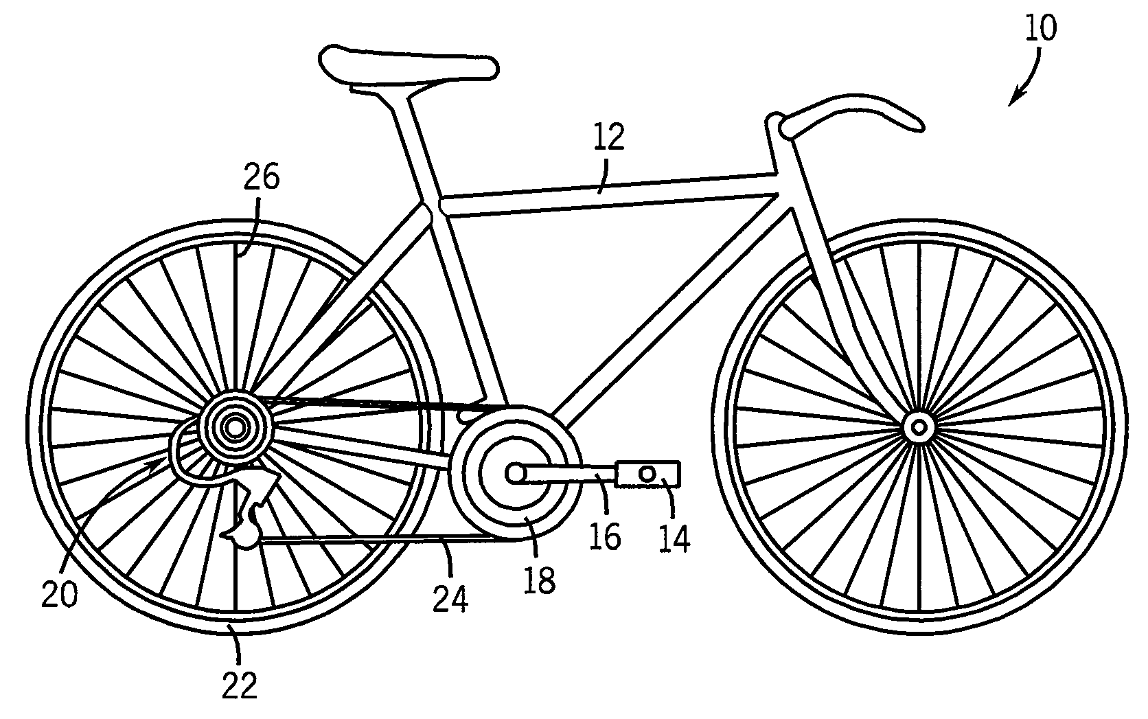
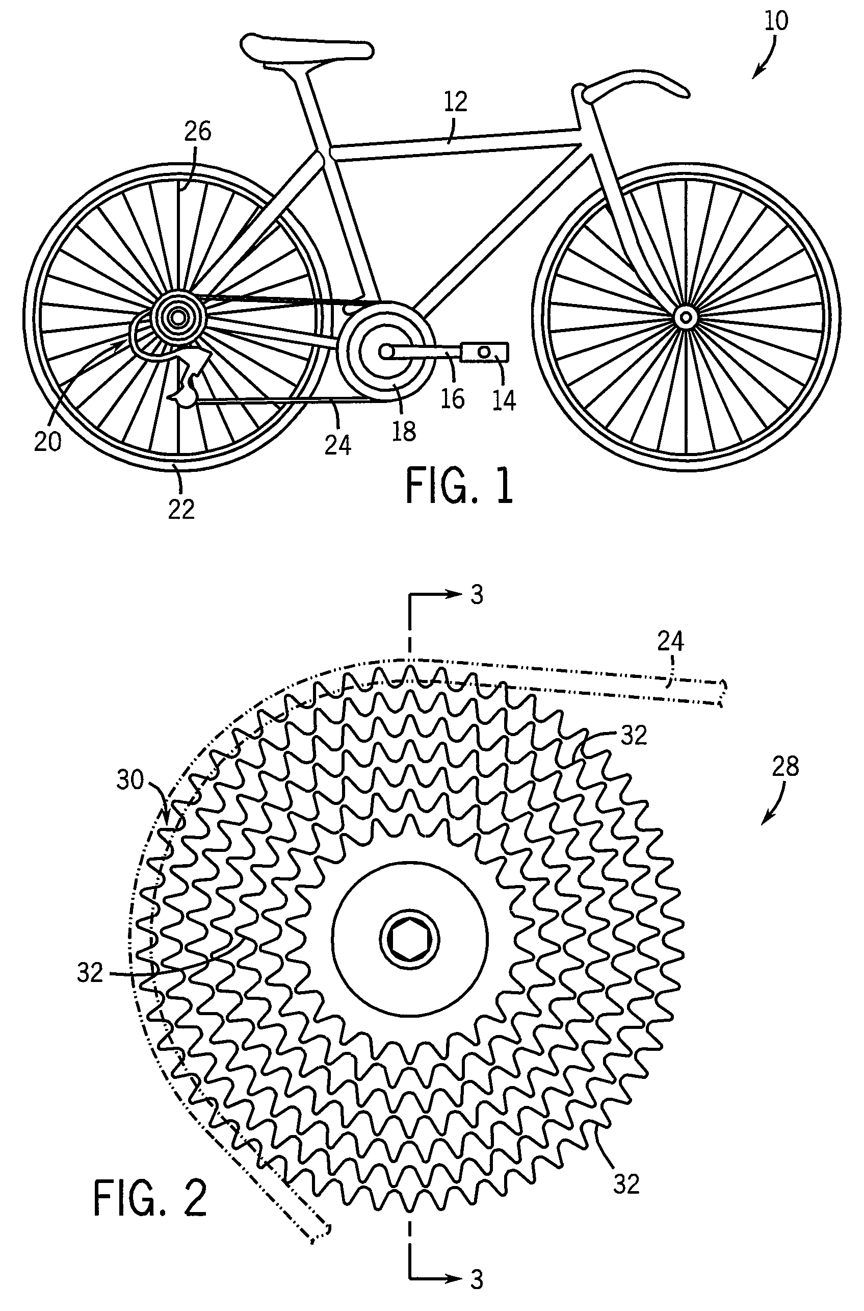
[0022]Turning now to the drawings, and initially to FIG. 1, a bicycle 10 equipped with a power sensing arrangement of the present invention is shown. The bicycle 10 includes a frame 12 that rotatably supports a pair of pedals 14 connected by crank arms 16 to a chain ring 18. The chain ring 18 is coupled to the hub 20 of the rear wheel 22 by a chain 24. The bicycle 10 is powered by a cyclist providing rotational forces to the chain ring 18 via the pedals 12 and crank arms 14. The rotation of the chain ring 18 is transferred by the chain 24 to the rear wheel hub 20, which carries the rear wheel 22 into rotation via spokes 26 to drive the bicycle 10 into motion.

[0023]Referring now to FIG. 2, the bicycle further includes a cassette 28 that is engaged with the chain 24 and attached to the rear hub 20 of the bicycle 10 in a known manner and includes a cogset 30 centrally disposed about a rear axle (not numbered) of the bicycle 10. The cogset 30 includes multiple sets of gear teeth 32 exte...


PUM

PropertyMeasurementUnit
torqueaaaaaaaaaa
compressiveaaaaaaaaaa
forceaaaaaaaaaa

Abstract

A cassette-based power measuring apparatus includes a power sensing arrangement mounted within a cavity defined by a hollow bicycle cassette. The power sensing arrangement includes a torque sensing assembly including torque sensing elements configured to measure a user applied torque. The torque sensing elements are in communication with an electronics assembly configured to process the measured data and transmit it to a receiver. The torque sensing assembly may comprise a torque tube or a series of bending beams secured between a rear plate of the cassette and a freehub. The torque tube or bending beams may include strain gauges bonded thereto for measuring strain induced by application of forces in response to user-applied power.

Description

BACKGROUND AND SUMMARY OF THE INVENTION[0001]The present invention relates to a power measuring device for use with a bicycle or other device that is powered by user operation of a pedal assembly and more particularly, to a power meter disposed within the cassette of a rear wheel assembly of a bicycle that measures the torque placed on the rear wheel assembly to determine the amount of power exerted by the user during operation of the pedal assembly.[0002]Bicycles, stationary trainers and fixed spinner bikes outfitted with a device used to sense or detect torque and / or power are generally known. One exemplary power meter is the POWERTAP, commercially available from Saris Cycling Group, Inc. of Madison, Wis. Another representative power meter is described in U.S. Pat. No. 6,418,797 to Ambrosina et al., the disclosure of which is incorporated herein by reference. The power meter described in the '797 patent is designed to measure the torque applied to the rear hub of the cycle. The ap...

Claims


Application Information

Patent Timeline
Patent Type & Authority Patents(United States)
IPC IPC(8): G01L3/10B62M1/36B62M9/12
CPCB62M9/12G01L3/1457B62K2207/00B62J45/411B62J45/42B62M1/00B62M6/00G01D11/245G01L3/00G01L3/24
Inventor ROESSINGH, JORDAN R.WENDT, DAVID L.
Owner SRAM CORPORATION
Why Eureka
Try Eureka