

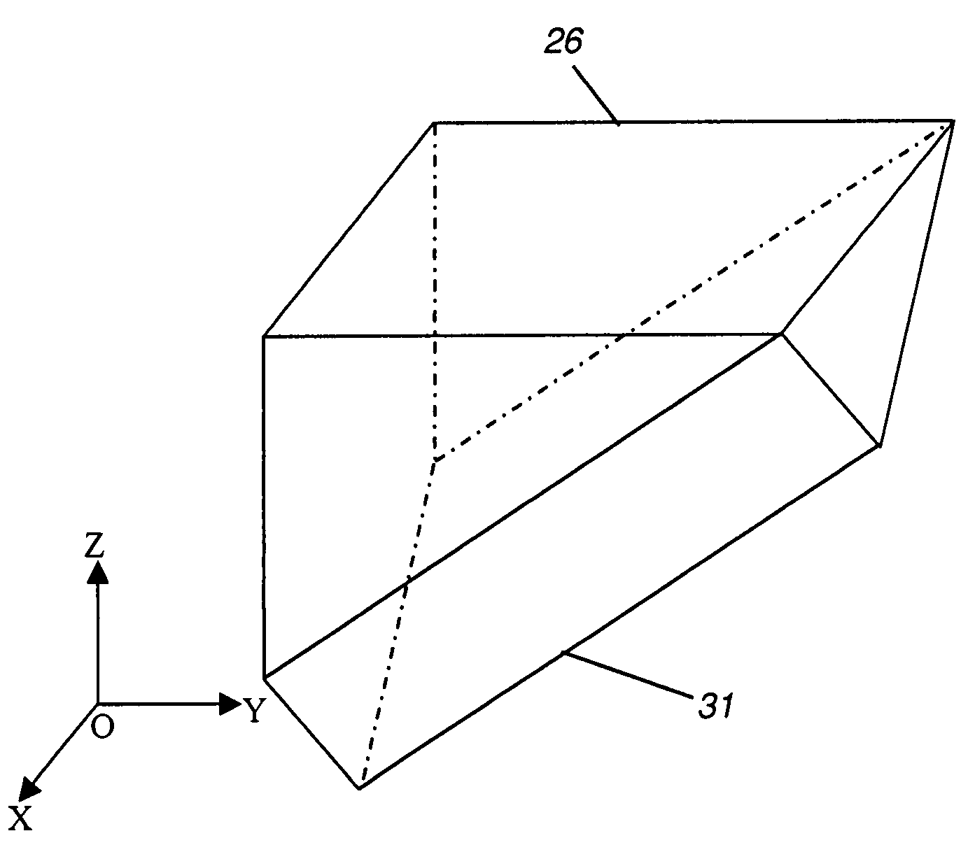
Turning film using array of roof prism structures
a technology of prism structure and array, applied in the field of two-dimensional turning film, can solve the problems of large divergence along the x-direction, unsatisfactory lcd display, large divergence of light, etc., and achieve the effect of more compact solution and higher on-axis brightness
- Summary
- Abstract
- Description
- Claims
- Application Information
AI Technical Summary
Benefits of technology
Problems solved by technology
Method used
Image

Examples
Embodiment Construction
[0039]The present description is directed in particular to elements forming part of, or cooperating more directly with, apparatus in accordance with the invention. It is to be understood that elements not specifically shown or described may take various forms well known to those skilled in the art.
[0040]Roof prisms, also termed dach prisms, provide right-angle deflection of incident light in various applications and are widely used in binoculars and other optical apparatus, particularly where compact packaging is desirable. As one example, U.S. Pat. No. 6,667,997 entitled “Optical Module and Method of Making the Same” to Nasu et al. discloses the deployment of a roof prism in a semiconductor laser module. Linear arrays of roof prisms have been disclosed for use in optical writing apparatus, such as that described in U.S. Patent Application Publication 2003 / 0007067 entitled “Imaging Device Array, Optical Writing Unit and Image Forming Apparatus” by Masuda et al.; in U.S. Pat. No. 5,9...
PUM
 Abstract
Description
Claims
Application Information