Turbine wheel

a turbine wheel and rotating shaft technology, applied in the field of turbine wheels, can solve the problems reducing the efficiency, and reducing the number of limitations, and achieve the effect of reducing the frontal area

Active Publication Date: 2010-08-17
FINNELL ALFRED W
View PDF11 Cites 13 Cited by
  • Summary
  • Abstract
  • Description
  • Claims
  • Application Information

AI Technical Summary

Benefits of technology

[0031]In yet another aspect, the deployed assembly can additionally include a rotational means, rotating about a vertical axis to reduce the frontal area respective to the airflow.

Problems solved by technology

This configuration provides several limitations.
A first limitation is efficiency.
A second limitation is the potential injury or death to birds.
This poses a risk whereby one of the blades could collide with the passing bird.

Method used


Image

  • Turbine wheel
  • Turbine wheel
  • Turbine wheel

Examples


Embodiment Construction

[0049]The following detailed description is merely exemplary in nature and is not intended to limit the described embodiments or the application and uses of the described embodiments. As used herein, the word “exemplary” or “illustrative” means “serving as an example, instance, or illustration.” Any implementation described herein as “exemplary” or “illustrative” is not necessarily to be construed as preferred or advantageous over other implementations. All of the implementations described below are exemplary implementations provided to enable persons skilled in the art to make or use the embodiments of the disclosure and are not intended to limit the scope of the disclosure, which is defined by the claims. Furthermore, there is no intention to be bound by any expressed or implied theory presented in the preceding technical field, background, brief summary or the following detailed description.

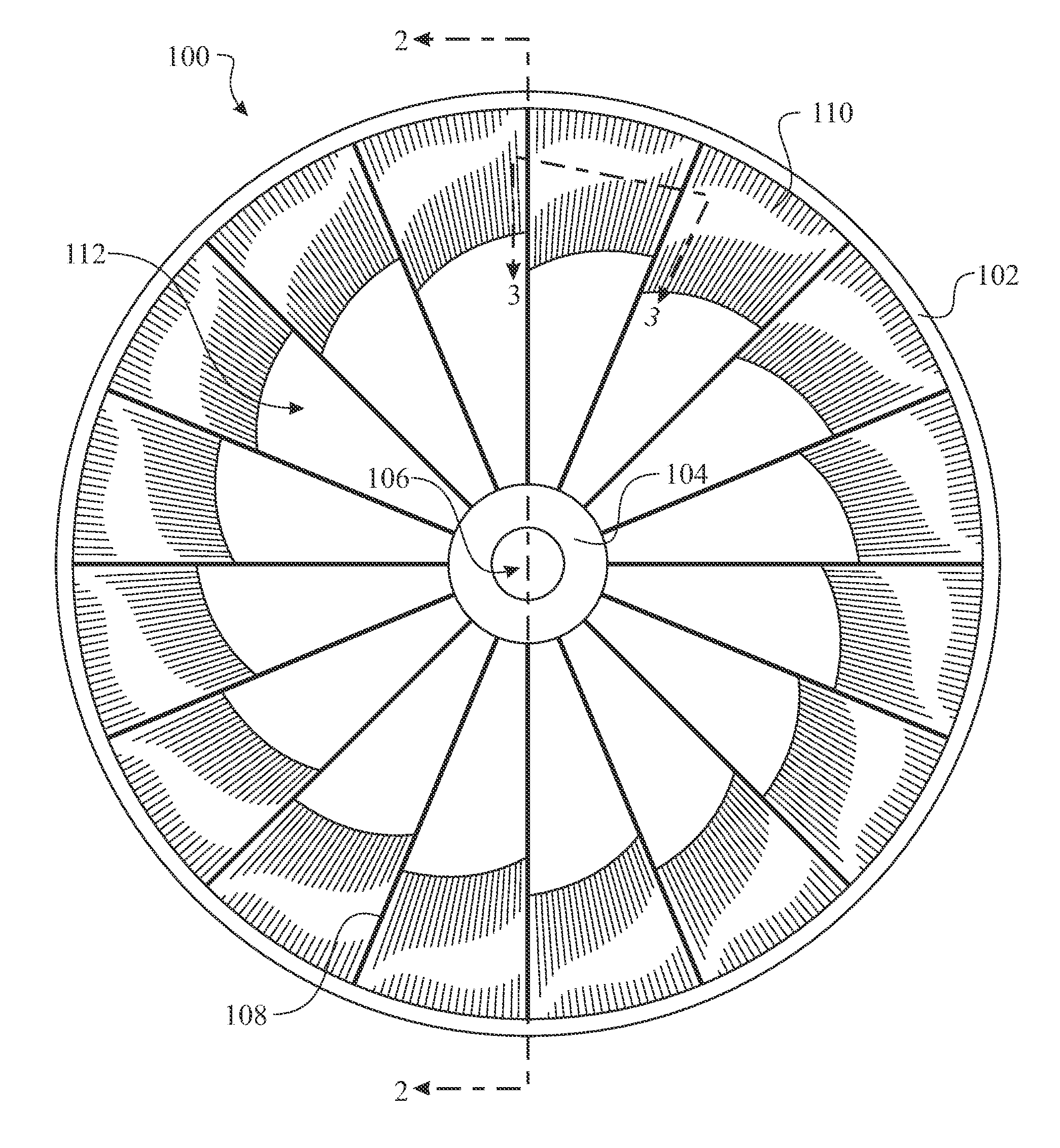
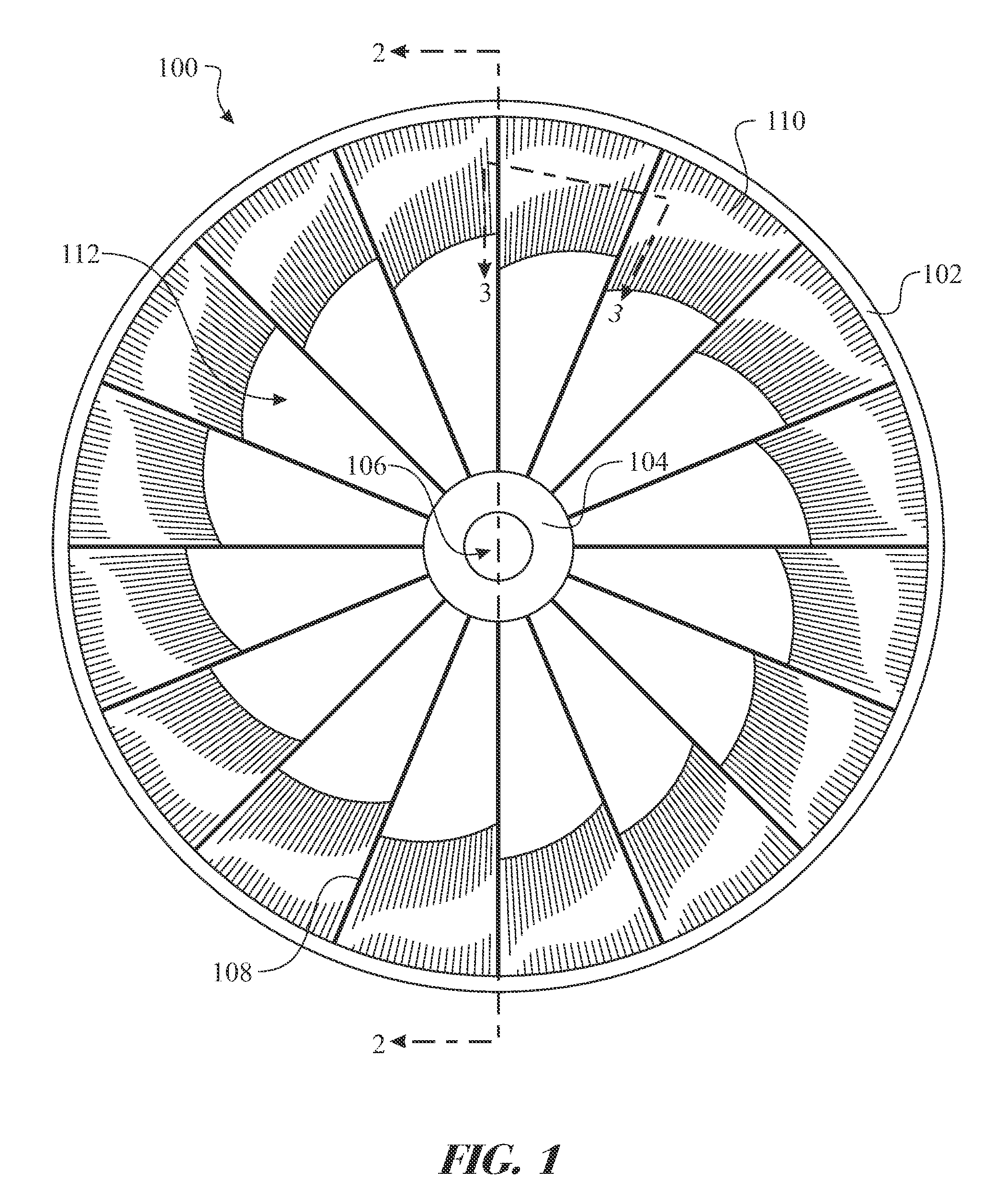
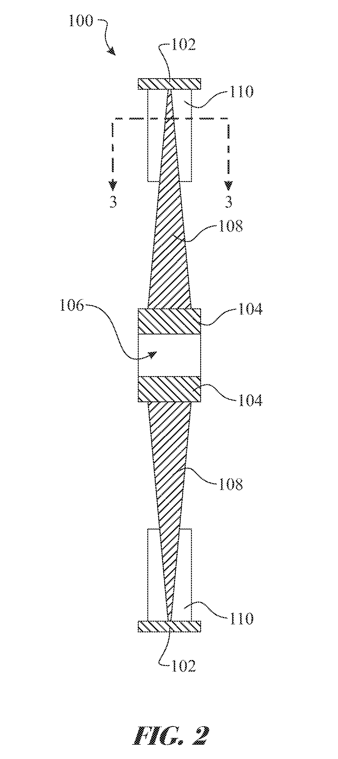
[0050]The present disclosure is generally directed to a turbine wheel 100 and the integrat...


PUM


Abstract

A wind driven energy source is providing utilizing a turbine wheel comprising a peripheral rim attached to a central hub via a series of spokes. A plurality of airfoil blades are assembled to the wheel, each blade being secured to a pair of spokes and positioned proximate an interior edge of the rim and extend only partially down the length of the spoke. This provides a central opening allowing airflow through the innermost region of the wheel. The blades are pivotally assembled to the spokes and can include an incident angle adjusting mechanism as well as a breakaway feature.

Description

FIELD OF THE INVENTION[0001]The present disclosure generally relates to an apparatus and method for converting wind to electrical energy. More particularly, the present disclosure relates to a turbine wheel having a plurality of blades disposed about an internal edge of a peripheral rim.BACKGROUND OF THE INVENTION[0002]Windmills and other wind driven turbines generally comprise a series of blades projecting radially from a centrally located hub. This configuration provides several limitations. A first limitation is efficiency. The energy utilized to turn an object is referred to as torque. The torque is calculated at a force times a distance from the center of rotation. The force applied near the center of rotation has a significantly lower impact than a force applied towards the outer edge of the blades, although resistance is created along the entire length of the blade. A second limitation is the potential injury or death to birds. Turbines of common windmills have a plurality of...

Claims


Application Information

Patent Timeline
Patent Type & Authority Patents(United States)
IPC IPC(8): F03D1/06
CPCF03D1/0658F03D1/0666F03D7/0224F05B2240/2211F05B2240/33F05B2260/79F05B2270/1016Y02E10/721Y02E10/723Y02E10/72
Inventor FINNELL, ALFRED W.
Owner FINNELL ALFRED W
Why Eureka
Try Eureka