Apparatus of catalyst-circulation type for decomposing waste plastics and organics, and system thereof
a technology of catalyst and organics, which is applied in the direction of physical/chemical process catalysts, metal/metal-oxide/metal-hydroxide catalysts, gaseous fuels, etc., can solve the problems of toxic gases, toxic substances such as dioxins, and plastics that are difficult to treat on discarding, etc., to achieve effective thermal energy use, enhance the effect of efficient decomposition, and suppress energy supply
- Summary
- Abstract
- Description
- Claims
- Application Information
AI Technical Summary
Benefits of technology
Problems solved by technology
Method used
Image
Examples
example 1
[0203]The air-supply blower 19 or the like as the carrier-gas supply means supplies air to the reactor 3. Then, the heating means 9 is actuated to heat the air supplied by the carrier-gas supply means. The heated air (hot air) is supplied into the reactor 3 containing the catalyst 2, thereby increasing the temperature of the catalyst 2 to a range from 420° C. to 560° C.
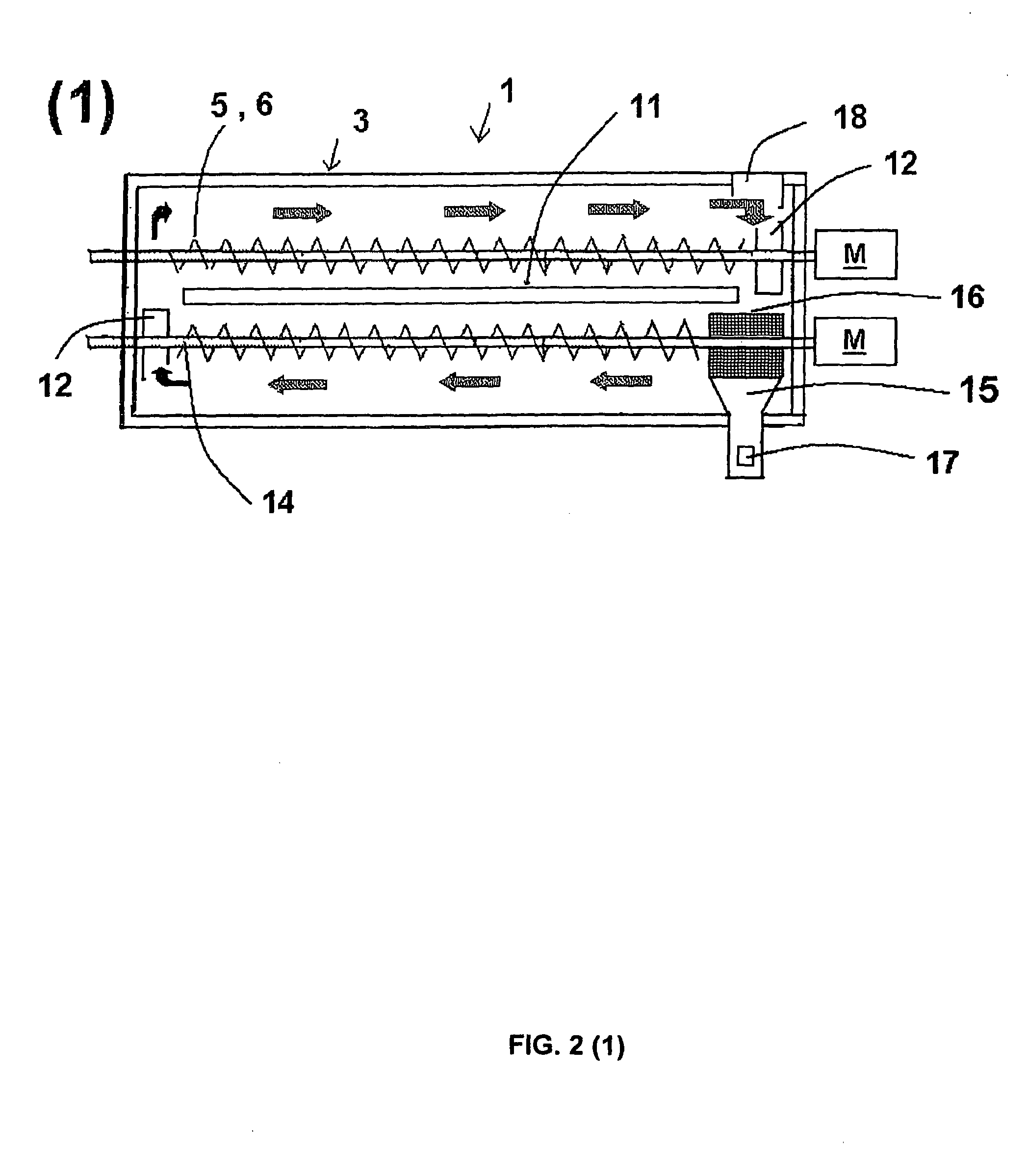
[0204]The crushing apparatus shown in FIG. 8 crushes medical waste to a size of several cubic millimeters and of larger than the size of the catalyst. The crushed medical waste is charged from the charge opening 7 of the reactor 3 into the concave portion 13, (refer to FIG. 2(4)). The charged medical waste circulates together with the catalyst 2 in the reactor by the action of the circulation means 5(D) and the circulation means 5. In the circulation step, the catalyst 2 and the medical waste are continuously agitated by the screw feeder as the agitation means 6, thus the contact between the catalyst 2 and the medical...
example 2
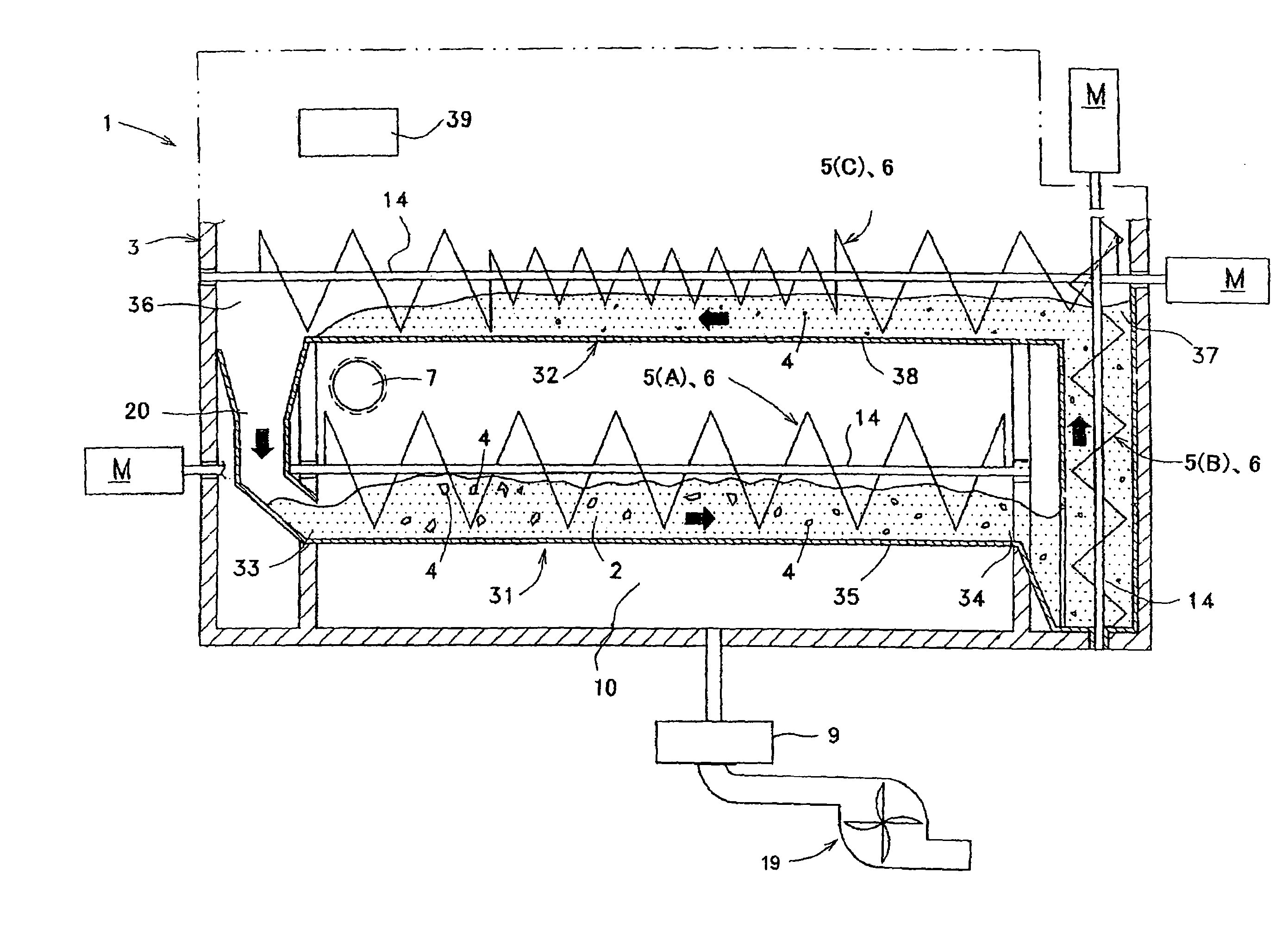
[0208]The charge opening 7 of the reactor 3, shown in FIG. 3, is opened, and the catalyst 2 is let flow down to near the upstream end 33 in the first stage tank 31. At the same time, the circulation means 5 is actuated. Thus, the circulation means 5(A) transfers the catalyst 2 firstly toward the discharge end 34 of the first stage tank 31, and to the lowermost end of the rotary shaft 14 of the circulation means 5(B). Succeedingly, the circulation means 5(B) pushes up the catalyst 2 to the charge end 37 of the second stage tank 32, and finally the circulation means 5(C) transfers the catalyst 2 to the downstream end 36 in the second stage tank 32. At this moment, the catalyst 2 exists and circulates in the circulation passage from the upstream end 33 in the first stage tank 31 to the downstream end 36 in the second stage tank 32.
[0209]When the circulation means 5 is kept operating while flowing down the catalyst 2 as described above, the catalyst 2 slides down through the returning p...
example 3
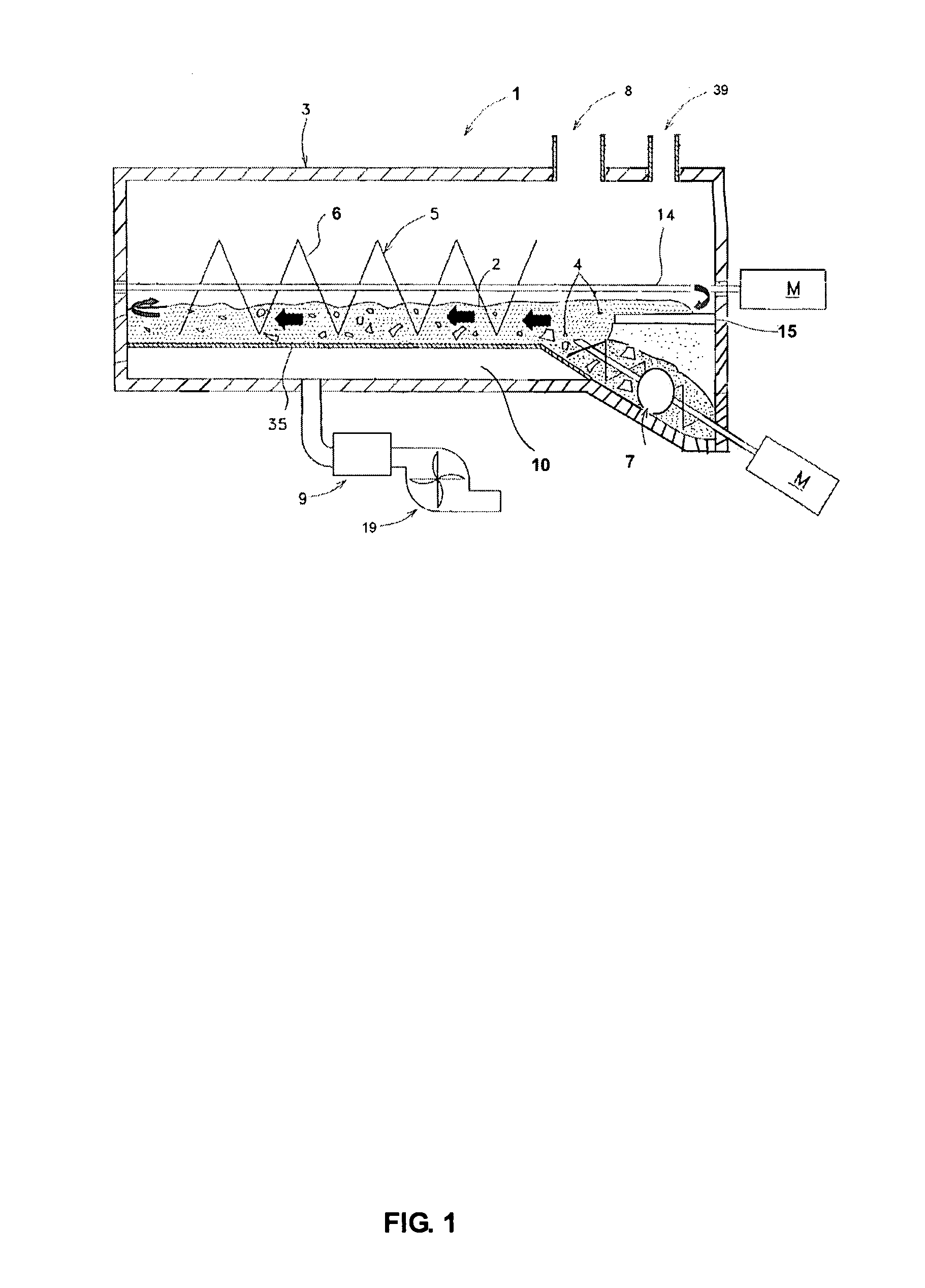
[0215]The charge opening 8 shown in FIG. 5 is opened, and the catalyst 2 is let flow down to near the upstream end 33. At the same time, the circulation means 5 is actuated. Thus, the circulation means 5 transfers the catalyst 2 firstly from the upstream end 33 toward the downstream end 36. At this moment, the catalyst 2 exists and circulates in the circulation passage from the upstream end 33 to the downstream end 36.
[0216]The flowing down of the catalyst 2 is stopped when the volume or mass of the catalyst 2 accumulated in the circulation passage reaches a desired value. After closing the charge opening, the heating means 9 heats the air supplied by the air-supply blower 19, and supplies the hot air to the reactor 3, thereby heating the catalyst 2 in the reactor 3 to a temperature range from 420° C. to 560° C. Since the catalyst is not deteriorated even retaining in the reactor, the succeeding decomposition operation can begin from the step of heating the catalyst 2 in the reactor...
PUM
| Property | Measurement | Unit |
|---|---|---|
| temperature | aaaaa | aaaaa |
| specific surface area | aaaaa | aaaaa |
| size | aaaaa | aaaaa |
Abstract
Description
Claims
Application Information
 - R&D
- Intellectual Property
- Life Sciences
- Materials
- Tech Scout
- Unparalleled Data Quality
- Higher Quality Content
- 60% Fewer Hallucinations
Browse by: Latest US Patents, China's latest patents, Technical Efficacy Thesaurus, Application Domain, Technology Topic, Popular Technical Reports.
© 2025 PatSnap. All rights reserved.Legal|Privacy policy|Modern Slavery Act Transparency Statement|Sitemap|About US| Contact US: help@patsnap.com


