Induction coupling apparatus

a technology of induction coupling and coupling shaft, which is applied in the direction of instruments, cores/yokes, base element modifications, etc., can solve the problems of difficult change of relative positions of magnetic cores and power lines, and achieve the effect of high reliability and satisfactory induction coupling efficiency

Inactive Publication Date: 2010-08-17
MITSUBISHI ELECTRIC CORP
View PDF3 Cites 28 Cited by
  • Summary
  • Abstract
  • Description
  • Claims
  • Application Information

AI Technical Summary

Benefits of technology

[0011]In view of the above, an object of the invention is to secure satisfactory induction coupling efficiency and high reliability.
[0012]The invention is an induction coupling apparatus used in a system for performing signal transmission with a power line used as a medium for transmitting a signal, the induction coupling apparatus for electro-magnetically coupling a signal line used as the medium for transmitting a signal to the power line and the power line through a magnetic core, wherein the magnetic core is formed from a first core element part and a second core element part so that a gap would be formed between the core element parts, the induction coupling apparatus comprising: a core parallel moving mechanism for carrying out relative and parallel movement of the first core element part and the second core element part in a direction that the length of the gap varies; and a predetermined gap length regulating member for limiting parallel movement in a direction that the first core element part and the second core element part approach each other to regulate the gap length to the predetermined gap length in the case that the core parallel moving mechanism is used for the parallel movement. Accordingly, the length of the gap can be easily and certainly made a predetermined length of the gap. This allows the satisfactory induction coupling efficiency and high reliability to be secured.
[0013]Further, the invention is an induction coupling apparatus used in a system for performing signal transmission with a power line used as a medium for transmitting a signal, the induction coupling apparatus for electro-magnetically coupling a signal line used as the medium for transmitting a signal to the power line and the power line through a magnetic core, comprising a clamp mechanism mounted to a main body part of the induction coupling apparatus for holding the power line on the both sides of the magnetic core in a direction of extension of the power line, wherein the clamp mechanism holds the power line to determine the relative positions of the magnetic core and the power line. Accordingly, the main body of the induction coupling apparatus is certainly mounted to the power line via the clump mechanism, so that the relative positions of the magnetic core and the power line are difficult to change due to a wind or such. This allows the satisfactory induction coupling efficiency and high reliability to be secured.

Problems solved by technology

Accordingly, the main body of the induction coupling apparatus is certainly mounted to the power line via the clump mechanism, so that the relative positions of the magnetic core and the power line are difficult to change due to a wind or such.

Method used


Image

  • Induction coupling apparatus
  • Induction coupling apparatus
  • Induction coupling apparatus

Examples


embodiment 1

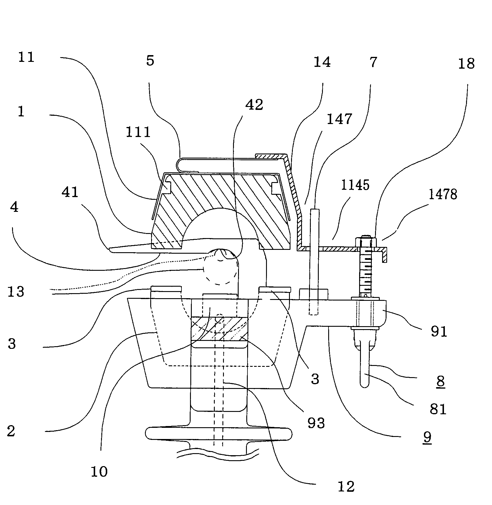
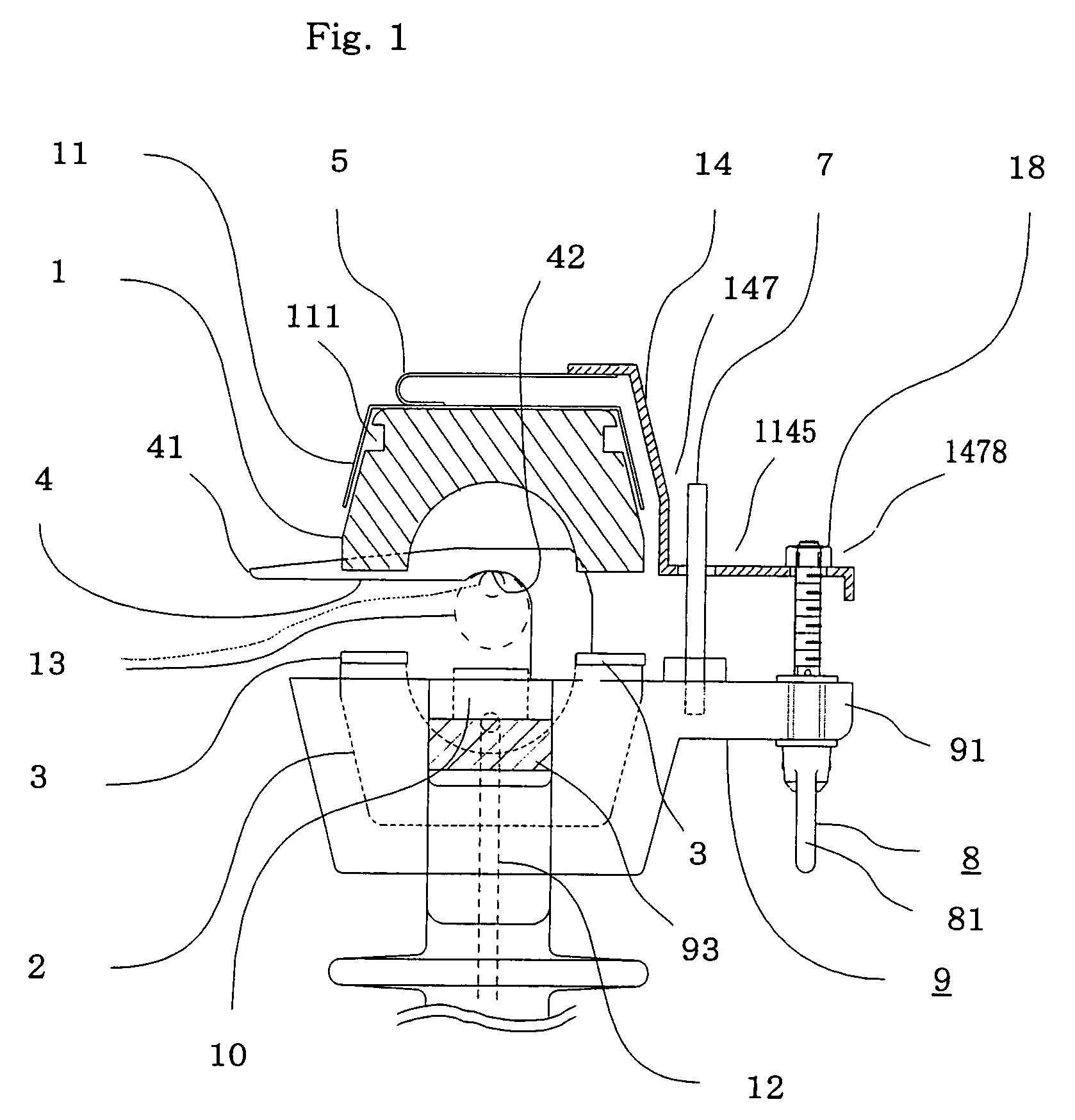
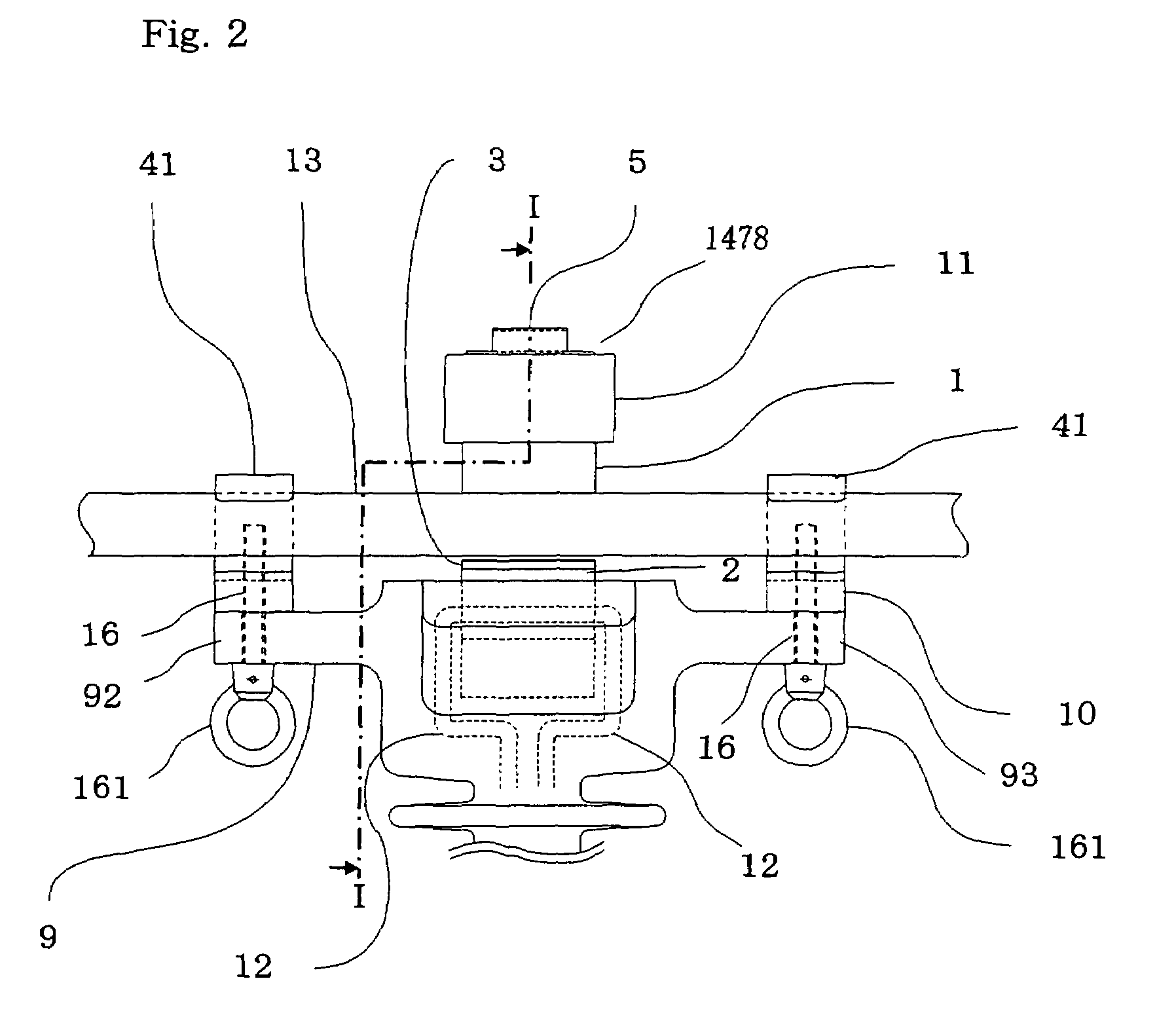
[0024]Embodiment 1 of the invention will be described hereinafter with reference to FIGS. 1 to 5. FIG. 1 is a vertically left side view of an example of an induction coupling apparatus in accordance with Embodiment 1 of the invention with a partially sectional view in a direction of an arrow along a line I-I in FIG. 2, showing a state that a first core element part is most separated from a second core element part by means of a core parallel moving mechanism. FIG. 2 is a front view of a whole structure of an induction coupling apparatus in accordance with Embodiment 1 of the invention, the view from the left side of FIG. 1. FIG. 3 is a vertically left side view corresponding to FIG. 1 of an induction coupling apparatus in accordance with Embodiment 1 of the invention, the induction coupling apparatus having a first core element part and a second core element part put close to each other by means of a core parallel moving mechanism so that the length of a gap would be a predetermined...

embodiment 2

[0065]A structure of an induction coupling apparatus in accordance with Embodiment 2 is substantially same as that of Embodiment 1 mentioned above. In the structure of the induction coupling apparatus in accordance with Embodiment 2, a clamp spacer 17 is provided under the power line fixing tool 10 as shown in FIG. 6.

[0066]The clamp spacer 17 is made so as to have the height corresponding to a change in diameter of the power line 13. The clamp spacer 17 is provided at the center thereof with a through hole 171 into which the fixing bolt 19 is inserted. The shape of the clamp spacer 17 can be simpler than that of the power line fixing tool 10 since only a function of adjusting the height is required.

[0067]An operation in Embodiment 2 is same as that of Embodiment 1 described above except for a point that the clamp spacer 17 is provided in advance in order to correspond to the power line 13 having a different diameter.

[0068]The above-mentioned structure of the induction coupling appar...

embodiment 3

[0069]An induction coupling apparatus in accordance with Embodiment 3 has a structure in which several structures are added to the structure of the induction coupling apparatus in accordance with Embodiment 1 described above and which is shown in FIGS. 7 and 8. In FIGS. 7 and 8, a position adjusting screw 6 is added. The upper core fixing spring 5 and the holding plate 14 are coupled by welding in Embodiment 1. In Embodiment 3, however, they are coupled by means of the position adjusting screw 6. A positioning pin fixing screw 15 is also added in FIG. 8.

[0070]The upper core fixing spring 5 is provided with a screw for the position adjusting screw 6. The holding plate 14 is provided with a through hole 142 into which the position adjusting screw 6 is inserted. The through hole 142 of the holding plate 14 has a diameter a little bit larger than the diameter of the position adjusting screw for the purpose of giving a space for adjustment by means of the position adjusting screw. The ho...


PUM

PropertyMeasurementUnit
lengthaaaaaaaaaa
gap lengthaaaaaaaaaa
heightaaaaaaaaaa

Abstract

To provide a structure capable of securing satisfactory induction coupling efficiency and high reliability in manufacturing an induction coupling apparatus used in power line carrier communication, the induction coupling apparatus having a magnetic core formed from a first core element part and a second core element part so that a gap would be formed between the core element parts, includes: a core parallel moving mechanism for carrying out relative and parallel movement of the first core element part and the second core element part in a direction that the length of the gap varies; and a predetermined gap length regulating member for limiting parallel movement in a direction that the first core element part and the second core element part approach each other to regulate the gap length to the predetermined gap length in the case that the core parallel moving mechanism is used for the parallel movement.

Description

BACKGROUND OF THE INVENTION[0001]1. Field of the Invention[0002]The present invention relates to a structure of an induction coupling apparatus used in power line carrier communication.[0003]2. Description of the Related Art[0004]An induction coupling apparatus is an apparatus for superposing a data signal on a power line by electromagnetic induction. Using a magnetic core surrounding a power line and an exciting coil surrounding the magnetic gore to apply signal electric current to the exciting coil generates the electromagnetic induction. The magnetic core is arranged to be able to be divided into two. A mechanism capable of separating and uniting the magnetic core having such a structure is used for mounting the magnetic core to the power line.[0005]In a conventional induction coupling apparatus, one side of the respective divided parts of the magnetic core having a structure divided into two is connected by means of a hinge while the other side is opened and closed, so that the ...

Claims


Application Information

Patent Timeline
Patent Type & Authority Patents(United States)
IPC IPC(8): H01F17/06
CPCH01F38/30H01F3/14H01F29/10G01R1/22
Inventor ZUMOTO, NOBUYUKIISOYA, HIROSHITSURIMOTO, TAKAOMURATA, YUICHIROHISAMORI, YOUICHI
Owner MITSUBISHI ELECTRIC CORP
Why Eureka
Try Eureka