

Network packet transmission mechanism
a network packet and transmission mechanism technology, applied in the field of communication systems, to achieve the effect of reducing lookup and complex operations, and simple distributed packet direction operations
- Summary
- Abstract
- Description
- Claims
- Application Information
AI Technical Summary
Benefits of technology
Problems solved by technology
Method used
Image

Examples
Embodiment Construction
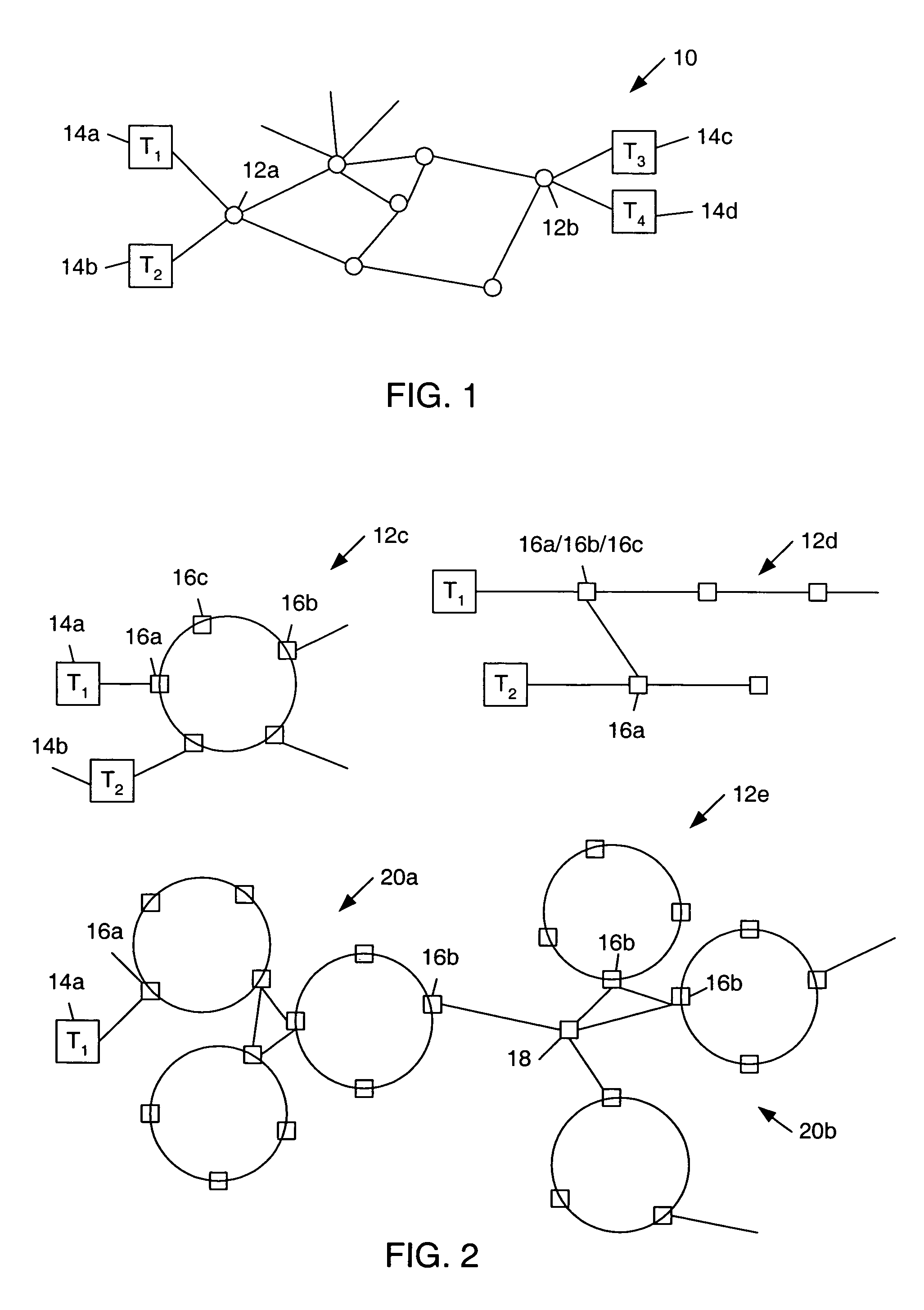
[0060]Turning now to the drawings, FIG. 1 illustrates a communication network 10. Network 10 includes an interconnection of subnets linked by nodes 12. Accordingly, network 10 can be thought of as one or more intranets or nodes 12 interconnected with one another, or interconnected via an interne.
[0061]Each node 12 can be thought of as embodying a subnet or a plurality of interconnected subnets. Select nodes 12a and 12b can be used to receive input or output data forwarded via termination devices 14. A termination device 14 includes any device which can forward input data or receive output data, popular forms of such input devices include a telephone or computer.
[0062]FIG. 2 illustrates exemplary forms of a node 12 and, more specifically, illustrates the connectivity and operation of modules or Routing Switches 16. For example, node 12c illustrates one example of a node comprising Routing Switches interconnected about a ring topography, oftentimes referred to as a “loop.” Coupled to ...
PUM
 Abstract
Description
Claims
Application Information