Device linkage control apparatus

a technology of linkage control and device, which is applied in the direction of frequency-division multiplex, testing/monitoring control system, instruments, etc., can solve the problems of complicated operation, inability to automatically carry out setting different details in a plurality of devices having different functions,

Active Publication Date: 2005-11-17
PANASONIC CORP
View PDF6 Cites 35 Cited by
  • Summary
  • Abstract
  • Description
  • Claims
  • Application Information

AI Technical Summary

Benefits of technology

[0014] According to the aforementioned second invention, it is possible to reduce, in the FP-Tree, separation of nodes of the same type into a plurality of nodes, and improve frequency pattern detection efficiency by constructing the structure of the FP-Tree created in the extraction of a life pattern in such a way that, with regard to every subtree within the FP-Tree, the element data with the highest frequency within the subtree necessarily becomes the root.
[0016] According to the aforementioned third invention, it is possible to reduce the number of times processing is required in the construction of the FP-Tree by using an order for incorporating input data into the FP-Tree, which has been rearranged according to a predetermined calculation procedure.
[0020] According to the fifth invention, it is possible to extract a co-occurrence pattern for device and contents usage which is dependent on an event which is characteristic of the user by taking the combination of devices and contents used by the user during a predetermined event.
[0024] According to the aforementioned seventh invention, when the user changes the timer setting details (preset time) of a random device, the timer linkage setting system identifies, using timer linkage information which is based on a predetermined user action pattern, the devices operating in linkage with the device that has had timer setting details changed, and automatically changes the respective timer setting details of the identified devices. Therefore, it is possible to reduce the complicated operations required of the user in the different timer settings of functions of the plurality of devices.
[0030] According to the aforementioned tenth embodiment, when the user cancels the timer setting of a random device, it is possible to have the timer management apparatus collectively cancel the timer settings of the other devices operating in linkage with the device that has had timer settings cancelled. Therefore, it is possible to reduce the operations required of the user in the timer cancellation of the plurality of devices.
[0032] According to the aforementioned eleventh invention, by using an interface included in a random device, it is possible to have the user verify the changed timer settings of the device that has had timer setting details changed by the timer management apparatus.

Problems solved by technology

In the case where a user uses a plurality of devices, all setting details of each function provided in the plurality of devices have to be set, requiring complicated operations.
However, although it is possible to carry out the same setting repeatedly for other devices by transmitting the presetting details to the plurality of devices in the aforementioned existing AV device system, setting different details in a plurality of devices having different functions cannot be carried out automatically.

Method used


Image

  • Device linkage control apparatus
  • Device linkage control apparatus
  • Device linkage control apparatus

Examples


first embodiment

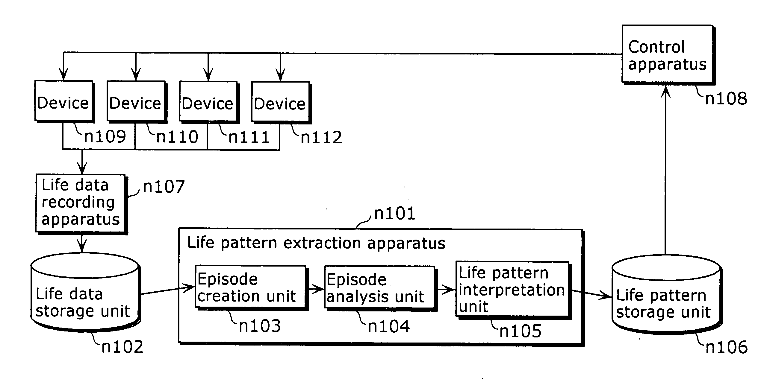
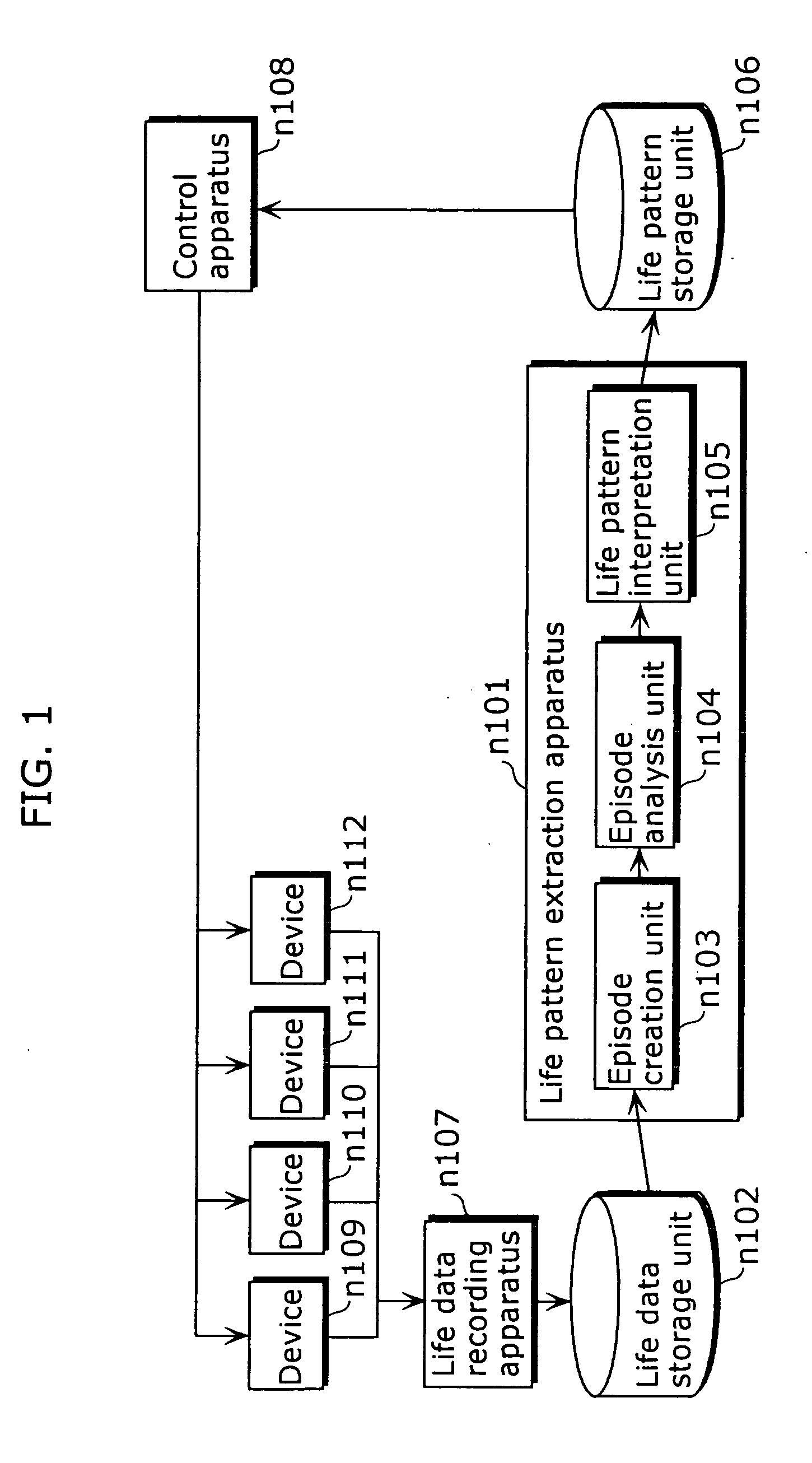
[0135]FIG. 1 is a block diagram showing the overall configuration of the device linkage control system in the first embodiment of the present invention. The device linkage control system is configured from a life pattern extraction apparatus n101, a life data storage unit n102, a life pattern storage unit n106, a life data recording apparatus n107, a control apparatus n108 and home appliances (devices) n109 to n112. Moreover, each of the modules (components) and devices are mutually connected via a wired network such as Ethernet (registered trademark) or a wireless network as represented by the 802.11b wireless network. Mutual transmission and reception of information, and controlling, is carried out via this network.

[0136] The home appliances n109 to n112 are devices such as a television, video deck, refrigerator, cooking range, or light.

[0137] The life data recording apparatus n107 is an apparatus that detects when a device is used by a user, generates life data indicating detai...

second embodiment

[0228] Next, the device linkage control system in the second embodiment of the present invention shall be explained. The second embodiment relates to an episode analysis unit that performs frequency pattern detection more efficiently for the episode analysis unit in the first embodiment by constructing an FP-Tree in which the unit of element data with the highest frequency among the element data included in a sub-tee becomes the root of the subtree, for all subtrees within the FP-Tree, in the episode analysis unit in the first embodiment.

[0229] In other words, the device linkage control system in the present embodiment has almost the same configuration as the device linkage control system in the first embodiment except for having the characteristic of including a new episode analysis unit n104a in place of the episode analysis unit n104.

[0230]FIG. 19 is a block diagram showing the structure of the episode analysis unit n104a in the present embodiment. The episode analysis unit n10...

third embodiment

[0248] Next, the device linkage control system in the third embodiment of the present invention shall be explained. The present embodiment relates to a process for changing the arrangement of the element data included in episode data so that an FP-Tree having the same structure as an FP-Tree constructed by the episode analysis unit n104a in the second embodiment is constructed by using only the episode analysis unit n104 in the first embodiment.

[0249]FIG. 28 is a block diagram showing the structure of the device linkage control system in the present embodiment. The device linkage control system in the present embodiment possesses almost the same configuration as the device linkage control system in the first embodiment except for including a new episode sorting unit n113 in life pattern extraction apparatus n101a, and including a simpler episode analysis unit 104b in place of the episode analysis unit n104 in the first embodiment.

[0250] The episode sorting unit n113 is a processin...


PUM


Abstract

A device linkage control system for controlling a plurality of devices in linkage with each other to suit the life pattern of a user, by extracting life pattern information of a user from an operating history of the plurality of devices, comprising: a life data recording apparatus (n107) for accumulating, in a life data storage unit (n102), usage information on the use of devices (n109 to n112) by the user, as life data; a life pattern extraction apparatus (n101) including an episode creation unit (n103) that takes, as element data, details related to an identified episode from among life data and creates episode data which is a combination of the element data, an episode analysis unit (n104) that analyzes relationships between the element data included in the episode data, and a life pattern interpretation unit (n105) that identifies, from the relationships between the element data, the life pattern which is characteristic of the user, and records this pattern, as life pattern information, in a life pattern storage unit (n106); and a control apparatus (n108) for linkage controlling of the devices (n109 to n112) by using the life pattern information of the user stored in the life pattern storage unit (n106).

Description

TECHNICAL FIELD [0001] The present invention relates to an apparatus for controlling a plurality of devices such as home appliances by linkage, and particularly to an apparatus for controlling the plurality of devices to suit a life of a user. BACKGROUND ART [0002] In the case where a user uses a plurality of devices, all setting details of each function provided in the plurality of devices have to be set, requiring complicated operations. [0003] So far, various control systems have been proposed in view of the problems involved in a plurality of settings such as this. [0004] For example, an AV device system has been proposed (official publication of Japanese Laid-Open Patent Application No. 11-177919 and so on) where, in a plurality of AV devices connected via a communication bus, an AV device in which timer presetting and execution are carried out notifies the timer presetting details to the AV devices operating in linkage with it, and the timer presetting of the AV devices operat...

Claims


Application Information

Patent Timeline
Patent Type & Authority Applications(United States)
IPC IPC(8): G05B23/02G06Q10/00G06Q50/00
CPCG05B23/0283
Inventor YOSHIDA, ATSUSHIARAKI, SHOUICHIKUTSUMI, HIROSHI
Owner PANASONIC CORP
Why Eureka
Try Eureka