
Charged Particle Beam Device with Aperture

a particle beam and aperture technology, applied in the field of charged particle beam devices, can solve the problems difficult to adjust the aperture during operation, and generally time-consuming alignment procedures, and achieves the effects of reducing the beam spot size, high spatial resolution, and simple construction and operation

Active Publication Date: 2007-11-08
ICT INTEGRATED CIRCUIT TESTING GESELLSCHAFT FUER HALBLEITERPRUEFTECHNIK GMBH
View PDF5 Cites 34 Cited by
  • Summary
  • Abstract
  • Description
  • Claims
  • Application Information

AI Technical Summary

Benefits of technology

[0011] It is yet a further aspect of the present invention to provide a charged particle beam device which provides more flexibility for adjusting the aperture size to optimize spatial resolution and beam current for any given application.
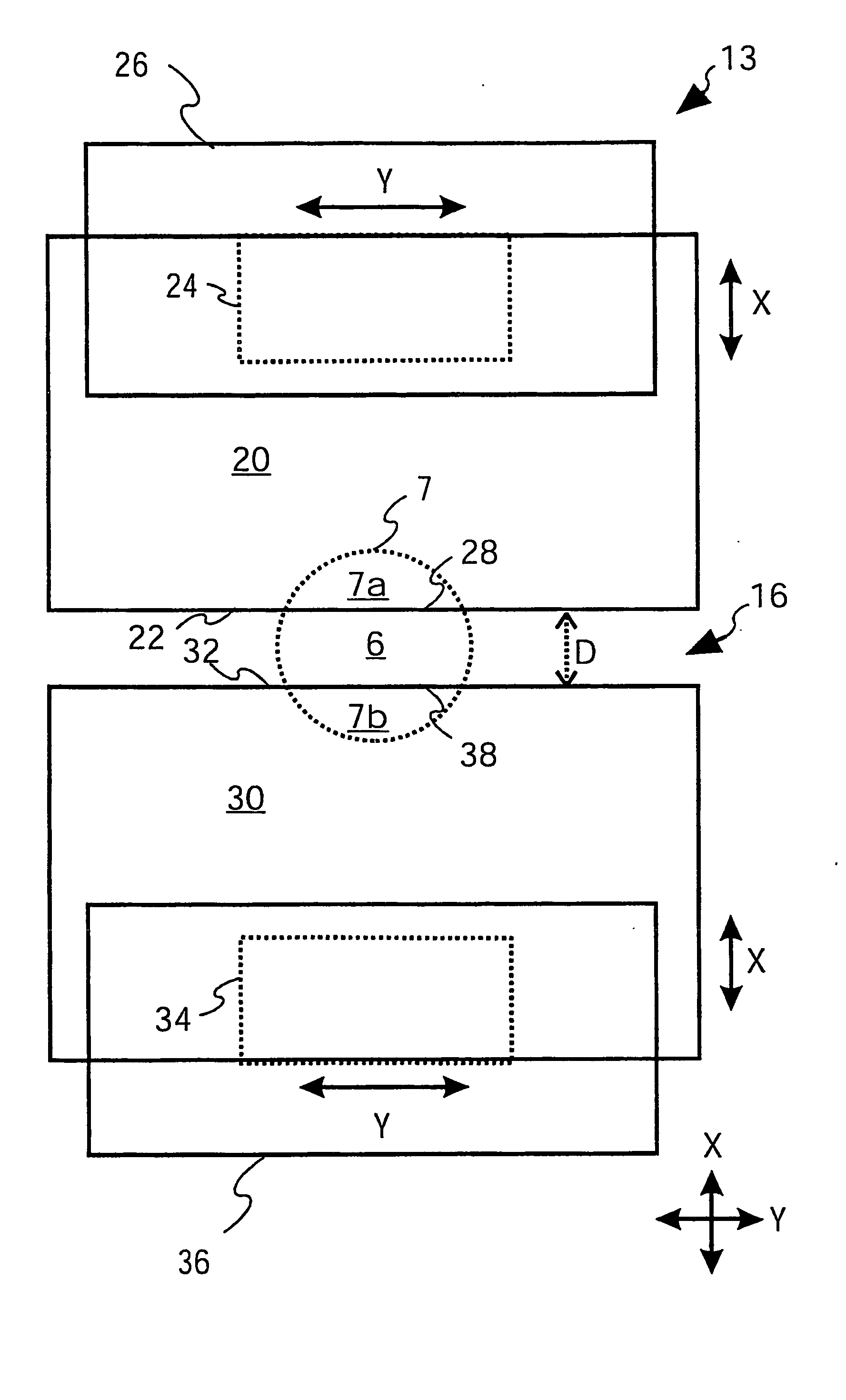
[0024] Preferably, the charged particle beam device with the aperture system of four members also includes a magnetic or electric octupole component. With the octupole component, it is possible to reduce the beam spot size by rounding the four corners of the rectangular shaped beam spot obtained from passing the beam through the aperture system. Since many charged particle beam devices are equipped with a magnetic or electric octupole component anyway, this method of focussing the charged particle beam is often easier to realize than installing and using eight movable members for defining the aperture.

Problems solved by technology

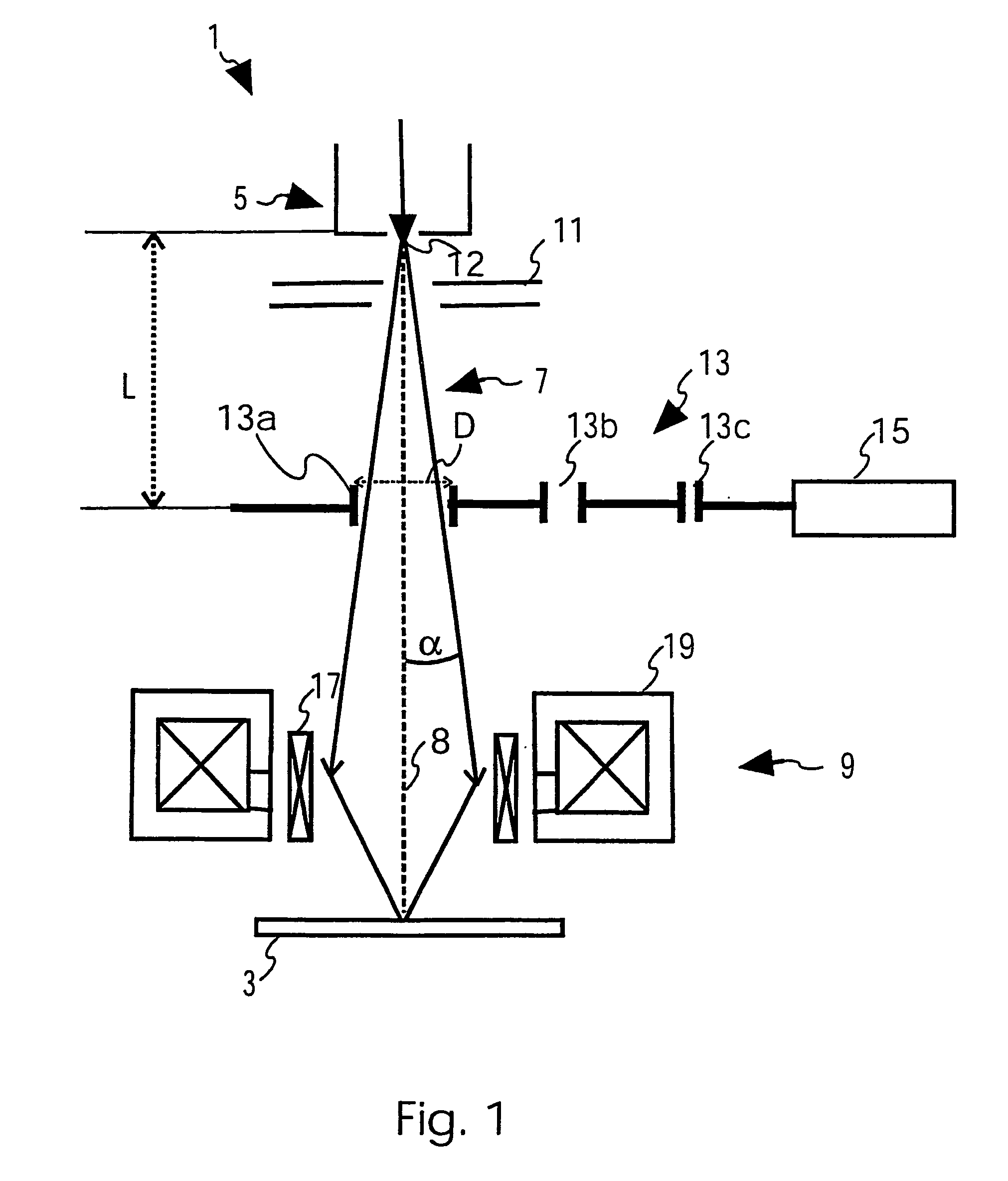
While it is true that aperture system 13 may be designed to have more than the three apertures of FIG. 1, the total number of apertures of a aperture system is always limited by tight space limitations and the constraint not to deter the electric field configuration within the beam column.
Such interruptions make it difficult to adjust the aperture during operation.
Such alignment procedure is generally time consuming.
For example, exposure to an electron beam generally leads to a contamination of the edges, while exposure to an ion beam generally leads to a removal of the aperture defining material.
Both effects cause the aperture angle to drift over time which in turn causes beam spot size and beam current to vary uncontrollably.

Method used


Image

  • Charged Particle Beam Device with Aperture
  • Charged Particle Beam Device with Aperture
  • Charged Particle Beam Device with Aperture

Examples


Embodiment Construction

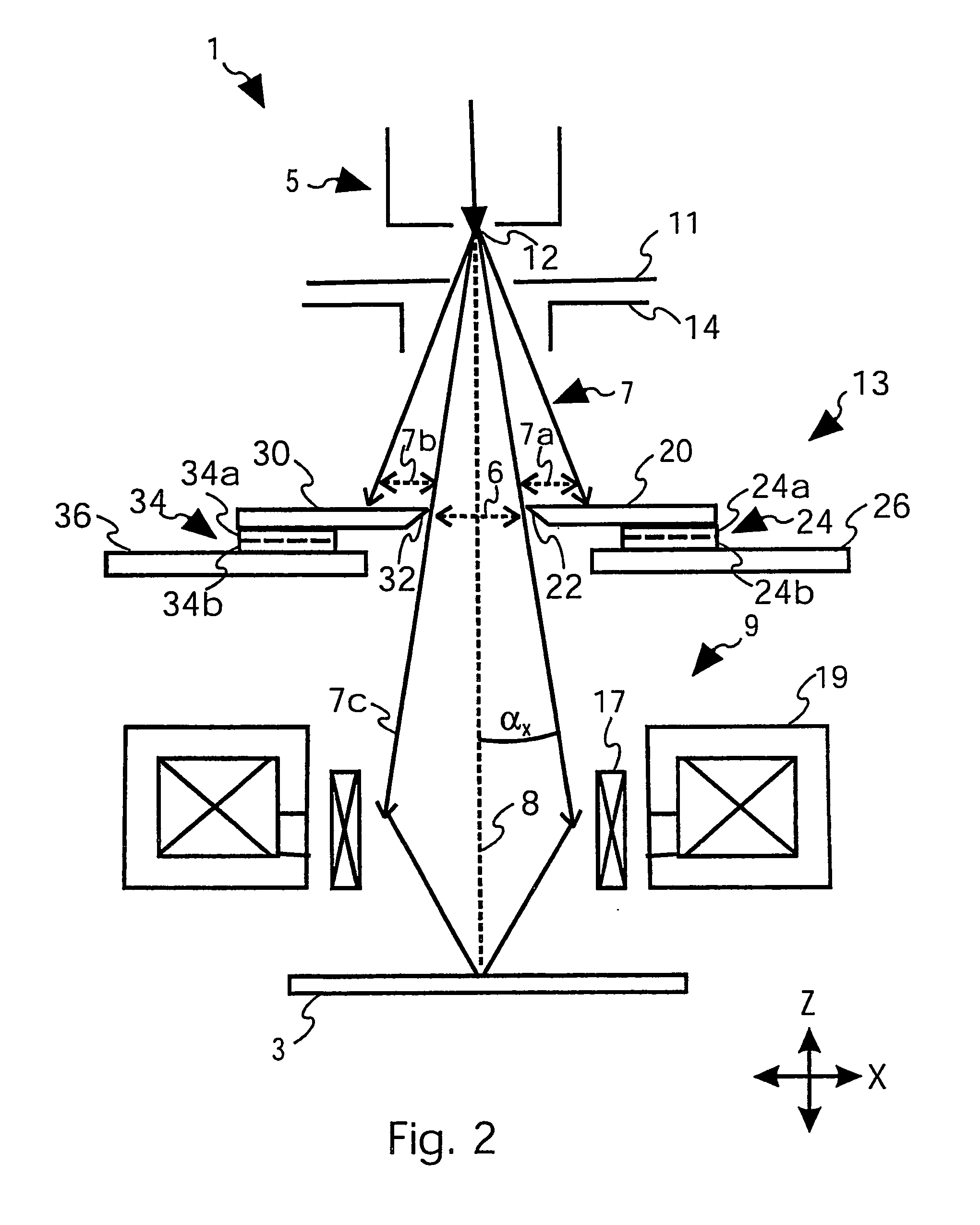
[0046] The term “charged particle beam device” in claim 1 refers to any device that uses a charged particle beam to probe or structure a specimen. Preferably, the charged particle beam device is a device for focussing the charged particle beam onto a specimen with a high spatial resolution. Preferably, the charged particle beam device includes a focussing lens for focussing an image of the charged particle beam source onto the specimen. Further, preferred, the charged particle beam device includes an aperture system having an aperture for defining an aperture angle at which the charged particle beam arrives at the focussing lens. Preferably, the aperture serves to limit the spherical and / or chromatic aberrations generated by the focussing lens. Further, depending on the application, a skilled person would know what other beam optical components to include to the charged particle beam device, like condensers, beam boosters, deflectors and the like.

[0047] By imaging the charged parti...


PUM


Abstract

The present invention relates to a charged particle beam device (1) for inspecting or structuring a specimen (3) comprising a charged particle beam source (5) to generate a charged particle beam (7), a focussing lens (9) to focus the charged particle beam (7) onto the specimen (3), and an aperture system (13) for defining an aperture (6) for the charged particle beam (7). The aperture system (13) includes a first member (20) to block a first portion (7a) of the charged particle beam (7) between the charged particle beam source (5) and the focussing lens (9), a second member (30) to block a second portion (7b) of the charged particle beam (7) between the charged particle beam source (5) and the focussing lens (9), first means (24) for moving the first member (20) to adjust the size of the blocked first portion (7a) of the charged particle beam (7), and second means (34) for moving the second member (30) independently from the first portion (7b). With such aperture system (13), it is possible to freely adjust the size of the aperture (6) and align it to the optical axis (8) during operation.

Description

FIELD OF THE INVENTION [0001] The invention relates to a charged particle beam device for inspecting or structuring a specimen. In particular, the present invention relates to a focussing charged particle beam device comprising an aperture for shaping the aperture angle of the charged particle beam. BACKGROUND OF THE INVENTION [0002] Charged particle beam devices are becoming increasingly important for imaging and structuring micro- and nanometer sized structures and devices. While electron beams are preferred for imaging, ion beams are more suitable for machining a specimen, for example, by using the ion beam for etching, cutting or deposition. [0003] For inspecting or structuring a specimen efficiently with a high spatial resolution, it is important that the aperture of the charged particle beam device is well matched to the operational set up. For example, for obtaining minimum charged particle beam spot size, or a maximum beam current at a given beam spot size, the aperture has ...

Claims


Application Information

Patent Timeline
Patent Type & Authority Applications(United States)
IPC IPC(8): H01J37/09
CPCH01J2237/0455H01J37/09
Inventor FROSIEN, JURGENLANIO, STEFANBANZHOF, HELMUT
Owner ICT INTEGRATED CIRCUIT TESTING GESELLSCHAFT FUER HALBLEITERPRUEFTECHNIK GMBH
Learn More