
Suspended gate cathode structure, electron gun, electron accelerator and irradiation device

A cathode structure and suspended grid technology, applied in the direction of linear accelerators, electrical components, accelerators, etc., can solve the problems of high average or pulse current, smaller effective emission surface 101 area, unfavorable problems, etc., and achieve the effect of increasing the average power

Active Publication Date: 2020-06-23
SHAANXI LIYOU BAIHUI TECH DEV CO LTD
View PDF7 Cites 0 Cited by
  • Summary
  • Abstract
  • Description
  • Claims
  • Application Information

AI Technical Summary

Problems solved by technology

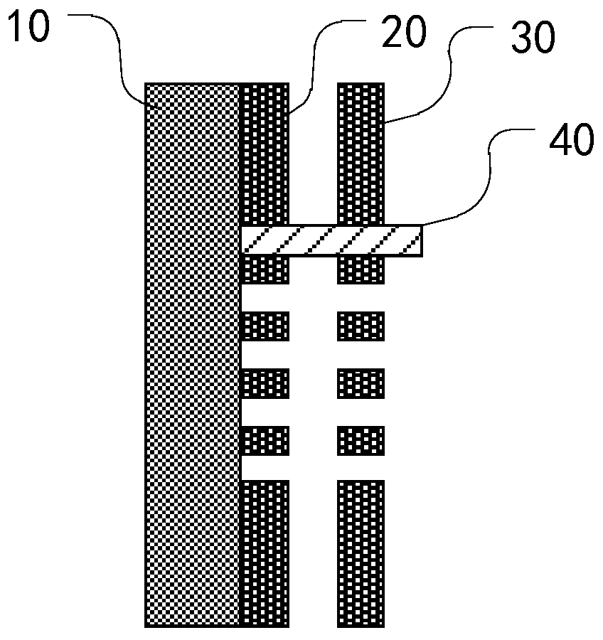
[0004] To reduce the interception current of floating gate, such as image 3 As shown, the design of the emitting surface of the cathode 10 in the related art is to coat a layer of emission-suppressing protective film 20 on the shadow part corresponding to the floating grid 30 on the surface to prevent the electron emission of this part, and at the same time require the effective emitting surface 101 (that is, the area not covered by the protective film) is slightly smaller, but this makes the area of ​​the effective emitting surface 101 smaller, only less than 50%, which is not conducive to obtaining a higher average or pulse current

Method used


Image

  • Suspended gate cathode structure, electron gun, electron accelerator and irradiation device
  • Suspended gate cathode structure, electron gun, electron accelerator and irradiation device
  • Suspended gate cathode structure, electron gun, electron accelerator and irradiation device

Examples


Embodiment Construction

[0032] Example embodiments will now be described more fully with reference to the accompanying drawings. Example embodiments may, however, be embodied in many forms and should not be construed as limited to the examples set forth herein; rather, these embodiments are provided so that this disclosure will be thorough and complete and fully convey the concept of example embodiments to those skilled in the art. The described features, structures, or characteristics may be combined in any suitable manner in one or more embodiments.

[0033] Furthermore, the drawings are merely schematic illustrations of the invention and are not necessarily drawn to scale. The same reference numerals in the drawings denote the same or similar parts, and thus repeated descriptions thereof will be omitted. Some of the block diagrams shown in the drawings are functional entities and do not necessarily correspond to physically or logically separate entities.

[0034] In this exemplary embodiment, f...


PUM


Abstract

The invention relates to an improved suspended gate cathode structure which can be better applied to an electron accelerator and an irradiation device. The suspended gate cathode structure comprises acathode body, a suppression emission gate and a suspended gate, wherein the cathode body is used for emitting electron beams; the suppression emission gate is located on one side of the emission surface of the cathode body, a preset gap is formed between the suppression emission gate and the cathode body, and the suppression emission gate is electrically connected to a power supply negative voltage end; and the suspended gate is located on the side, which deviates from the cathode body, of the suppression emission gate.

Description

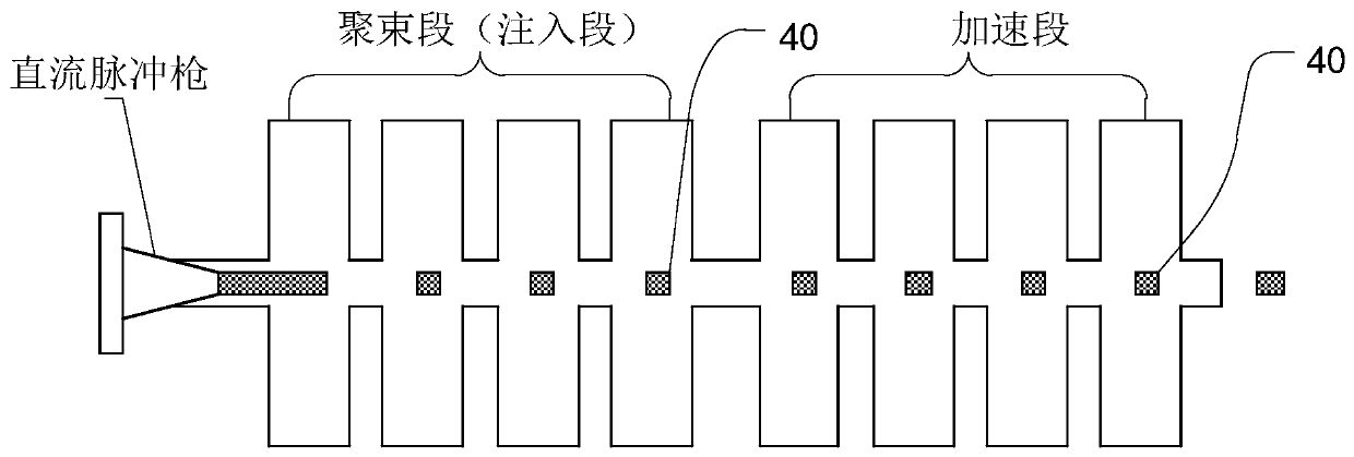
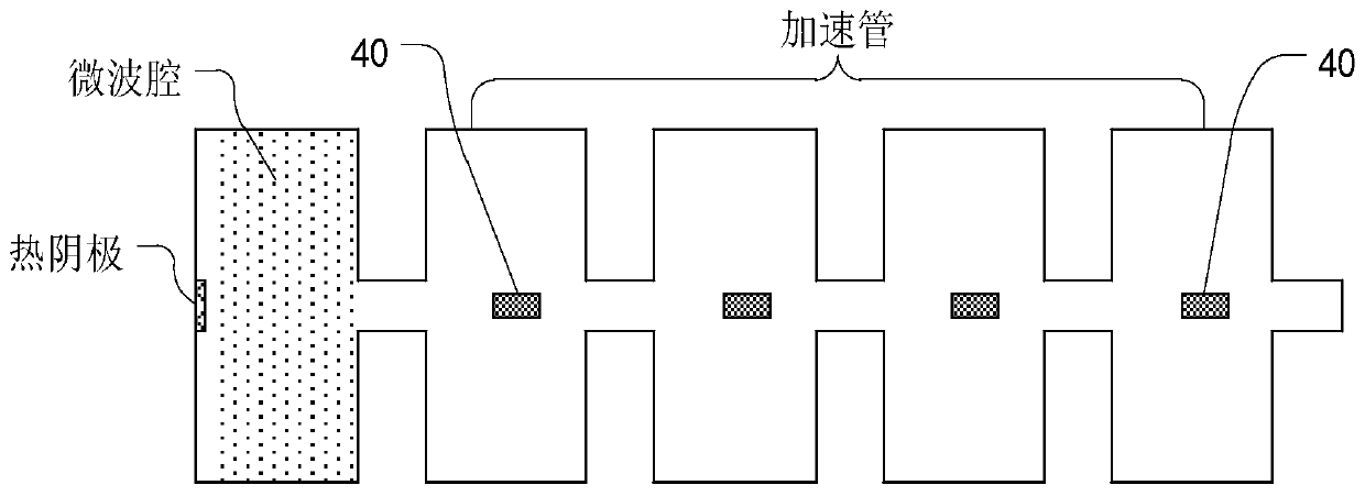
technical field [0001] The disclosure relates to the technical field of electron accelerators, in particular to an improved suspension grid cathode structure, an electron gun, an electron accelerator and an irradiation device. Background technique [0002] With the development of science and technology, the application fields of electron accelerators are becoming more and more extensive. Electron linear accelerator is the most widely used accelerator. It is widely used in tumor treatment, polymer cross-linking, disinfection of medical supplies, flaw detection of castings, food preservation, customs inspection, sterilization and insecticide, isotope production and scientific research. . Conventional electron linear accelerators such as figure 1 As shown, it is mainly composed of DC section, bunching section and acceleration section. Since the acceleration section can only accelerate the micro-pulse electron beam composed of discrete bunches, the lower-energy DC electron be...

Claims


Application Information

Patent Timeline
IPC IPC(8): H05H7/22H05H9/00
CPCH05H7/22H05H9/00
Inventor 畅祥云
Owner SHAANXI LIYOU BAIHUI TECH DEV CO LTD
Learn More