Active optical cable electrical connector

a technology of active optical cable and electrical connector, which is applied in the direction of optics, fibre mechanical structures, instruments, etc., can solve the problems of inability to terminate in the field, 0.4′′ or 10 mm in diameter, and difficult to achieve potential solutions

Active Publication Date: 2010-08-17
II VI DELAWARE INC
View PDF136 Cites 54 Cited by
  • Summary
  • Abstract
  • Description
  • Claims
  • Application Information

AI Technical Summary

Problems solved by technology

As bandwidth requirements increase, potential solutions become more difficult to accomplish, especially with copper-based solutions.
This cable is quite bulky (typically about 0.4″ or 10 mm in diameter) and expensive to make and cannot be terminated in the field (as can CAT-5 for example).
Furthermore, this copper-based 10 G solution is limited to distances of about 15 m without special efforts.
Alternative copper-based 10 G solutions are being developed and standardized but are likely also to require significant power consumption.
However it is expected that because of the extremely complex signal processing required, this standard will require circuitry with very high power dissipation, initially as high as 8-15 Watts (per port and thus twice this per link).
These high power levels represent both a significant increase in operating costs and perhaps more importantly, limitations on the density of ports which can be provided on a front panel.
Nevertheless, because of the cost of present day optical solutions at 10 G, there remains interest in this copper solution.

Method used


Image

  • Active optical cable electrical connector
  • Active optical cable electrical connector
  • Active optical cable electrical connector

Examples


Embodiment Construction

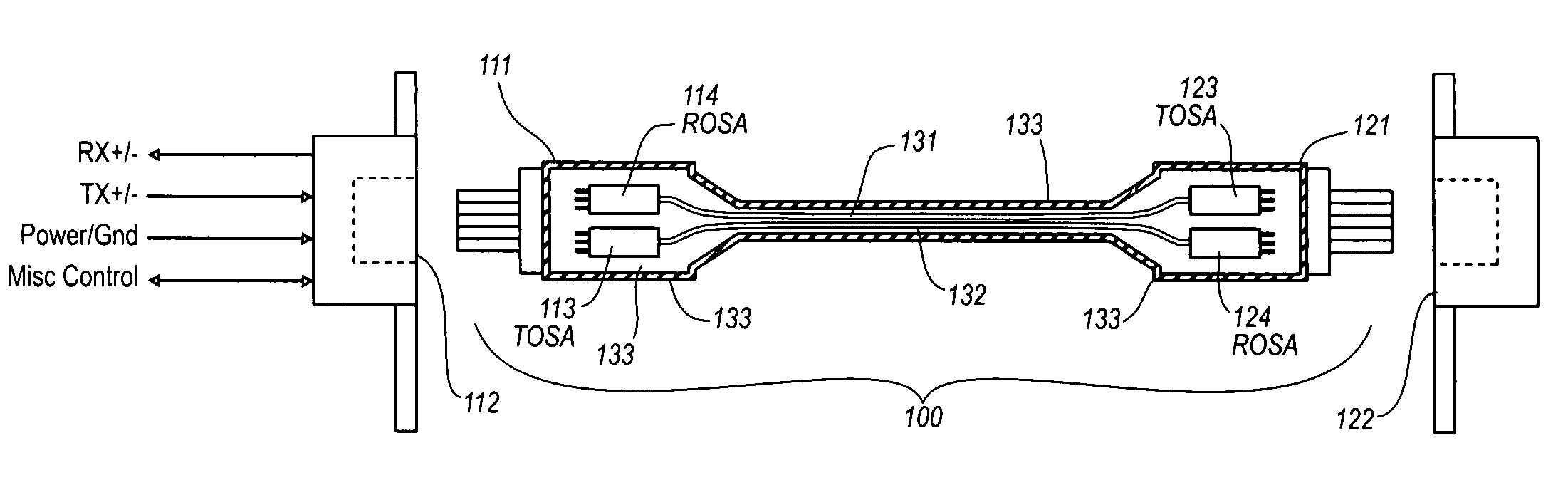
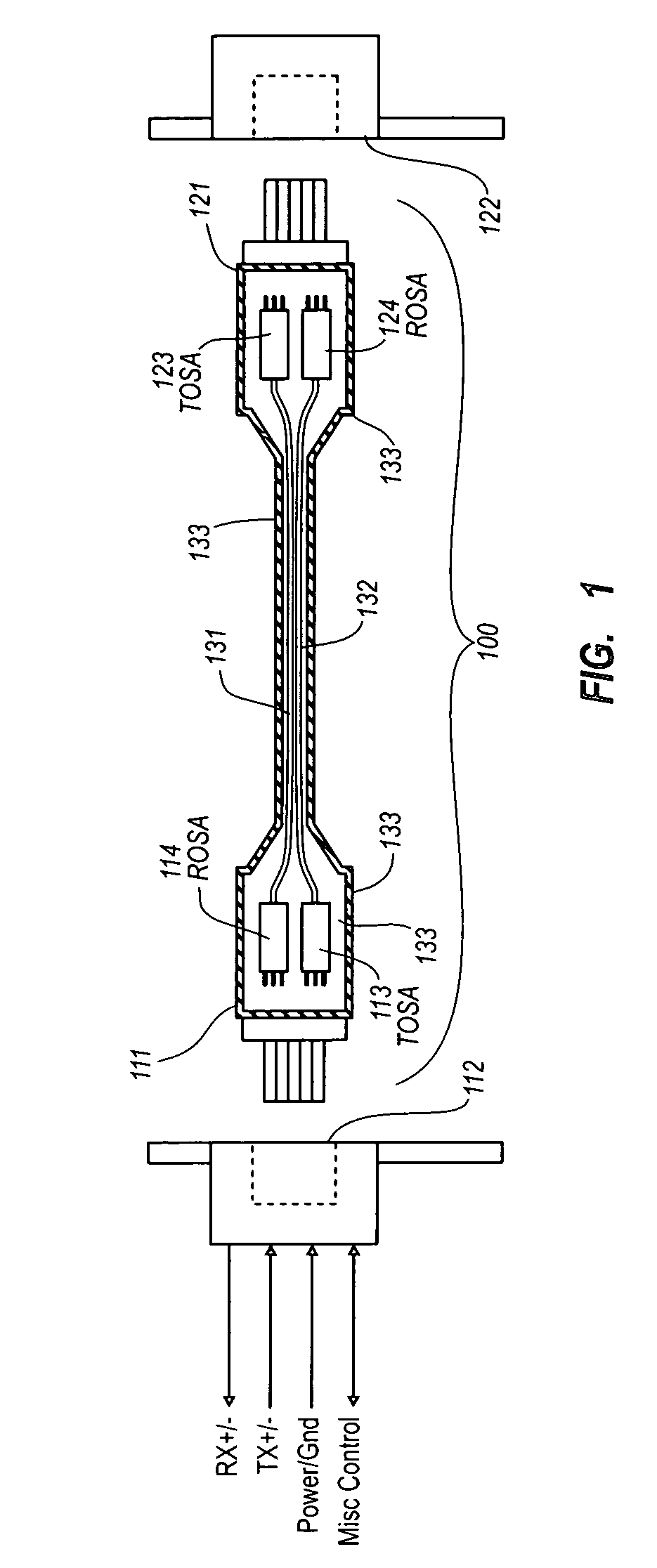
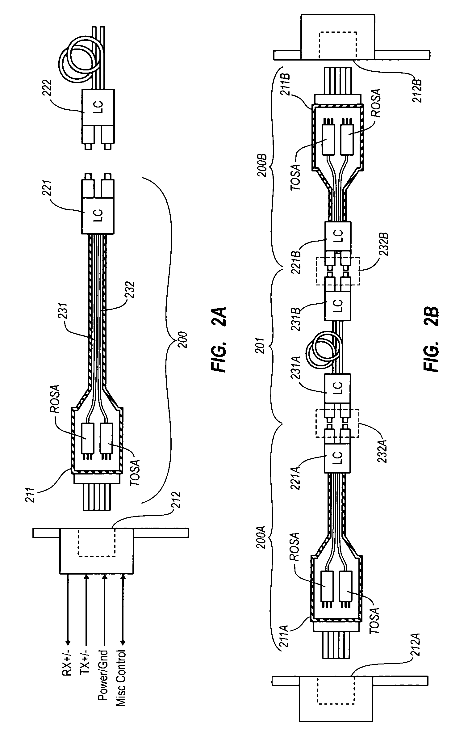
[0056]Embodiments of the present invention relate to the use of a communication cable that is exposed at least at one end using an electrical connection, while communicating over much of its length using optical fiber. Thus, those designing or selecting networking equipment or administrating network nodes need not choose a copper-based solution or an optical solution in communicating over a network. Instead, the network node need only have an electrical port of some type to thereby support either copper-based communication or optical communication. In addition to network applications, such a cable can support point to point high speed serial connections such as the transmission of serialized video data from source to a display. The communication over the optical fiber may be high speed and suitable for 10 G applications and higher. As will described below, cable designs which are purely electrical but mechanically and electrically interoperate with the optical cables described herei...


PUM


Abstract

An electrical connector that is integrated within an active cable at one end of the active cable, wherein the active cable is configured to communicate over much of its length using one or more optical fibers. The cable may be an electrical to optical cable, and electrical to electrical cable, or one of many other potential configurations.

Description

BACKGROUND[0001]Communication technology has transformed our world. As the amount of information communicated over networks has increased, high speed transmission has become ever more critical. High speed communications often rely on the presence of high bandwidth capacity links between network nodes. There are both copper-based solutions and optical solutions used when setting up a high bandwidth capacity link. A link may typically comprise a transmitter that transmits a signal over a medium to a receiver, either in one direction between two network nodes, or bi-directionally. An optical link might include, for example, an optical transmitter, a fiber optic medium, and an optical receiver for each direction of communication. In duplex mode, an optical transceiver serves as both an optical transmitter that serves to transmit optically over one fiber to the other node, while receiving optical signals over another fiber (typically in the same fiber-optic cable).[0002]Presently, commun...

Claims


Application Information

Patent Timeline
Patent Type & Authority Patents(United States)
IPC IPC(8): G02B6/36G02B6/44
CPCG02B6/4292G02B6/4416G02B6/4284
Inventor ARONSON, LEWIS B.DOUMA, DARIN J.TOGAMI, CHRIS KIYOSHI
Owner II VI DELAWARE INC
Why Eureka
Try Eureka