Method and system for positioning a device in a tubular organ

a technology of tubular organs and positioning devices, which is applied in the field of positioning devices in tubular organs of the body, can solve the problems of increasing the risk of artery injury, total blockage of the treated artery, and significantly increasing the chance of subsequent renarrowing of the artery

Inactive Publication Date: 2010-08-17
PAIEON INC
View PDF79 Cites 224 Cited by
  • Summary
  • Abstract
  • Description
  • Claims
  • Application Information

AI Technical Summary

Benefits of technology

[0012]In accordance with the invention, positioning of the device in a tubular organ, such as an artery is performed utilizing a three-dimensional computer reconstruction of the organ. In the case of an artery, a three-dimensional reconstruction of the artery may be displayed on a monitor screen from any selected perspective. This allows a diseased artery, for example, to be viewed in the reconstruction from a perspective that is optimal for assessing the morphology and the length of disease in the artery. This in turn permits accurate determination of a location where an intravascular device should be deployed. A three-dimensional reconstruction of an artery may be obtained for example, as disclosed in Applicant's WO 01 / 85030 entitled “System and Method for Three-Dimensional Reconstruction of an Artery ” published on Nov. 15, 2001. The reconstruction is displayed on a monitor screen, and the location where the device is to be deployed is determined and marked in the reconstruction taking into consideration the abnormality characteristics, the nominal dimensions of the device and its dimensions after deployment.

Problems solved by technology

Once the device is positioned within the artery and deployed, repositioning of the device is either impossible or may significantly increase the risk of injury to the artery and can result in total blockage to the treated artery.
Improper positioning of a stent at the diseased site within the artery, or use of a longer stent than is actually required in order to compensate for inaccurate positioning, may significantly increase the chance for subsequent renarrowing of the artery.
Moreover, in atherectomy procedures, inaccurate positioning and deployment of the device in the artery may cause a fatal thrombosis.
Since many images may be required, the total amount of contrast material released into the blood may be quite large and harmful to the patient.
Moreover, determining the location of the device in an artery in relation to the region to be treated is often inaccurate by this method.
It does not teach how to use such a method to navigate a tool located side a tubular organ to a pre-defined position within the tubular organ.

Method used


Image

  • Method and system for positioning a device in a tubular organ
  • Method and system for positioning a device in a tubular organ
  • Method and system for positioning a device in a tubular organ

Examples


Embodiment Construction

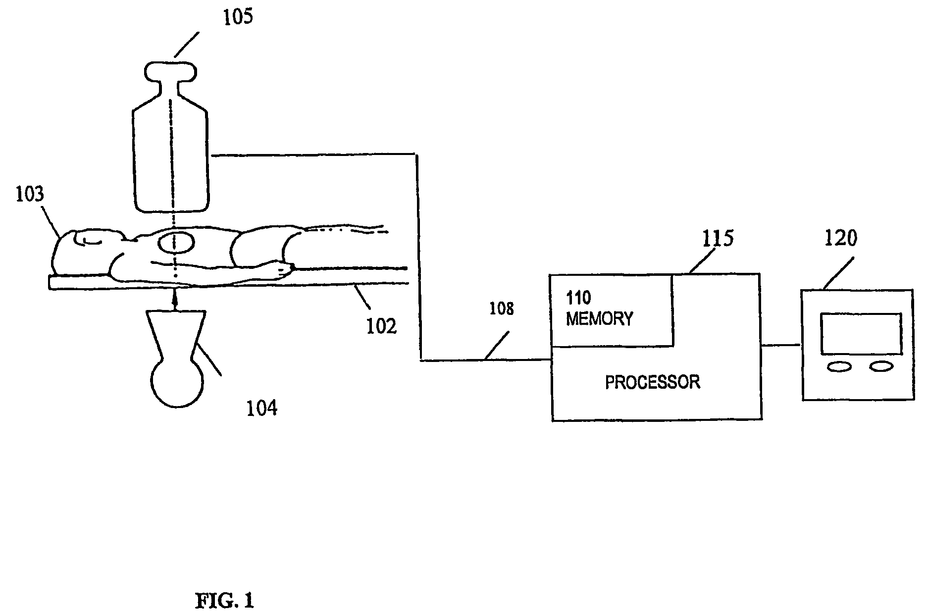
[0040]Referring first to FIG. 1, shown is a system for positioning a catheter or intravascular device at a desired location within an artery in accordance with one embodiment of the invention. The system comprises a table 102 upon which a patient 103 lies. An X-ray source 104 is located under the table 102 for projecting X-rays through the patient 103 to an X-rays camera 105 located above the table 102, diametrically opposite the X-rays source 104. The X-ray camera 105 generates video signals 108 representing one or more X-ray images of the patient 103. The video signals 108 are stored in a memory 110 of a processor 115. Images captured by the X-ray camera 105 may be viewed on a monitor 120 either in real-time or after being retrieved from the memory 110.

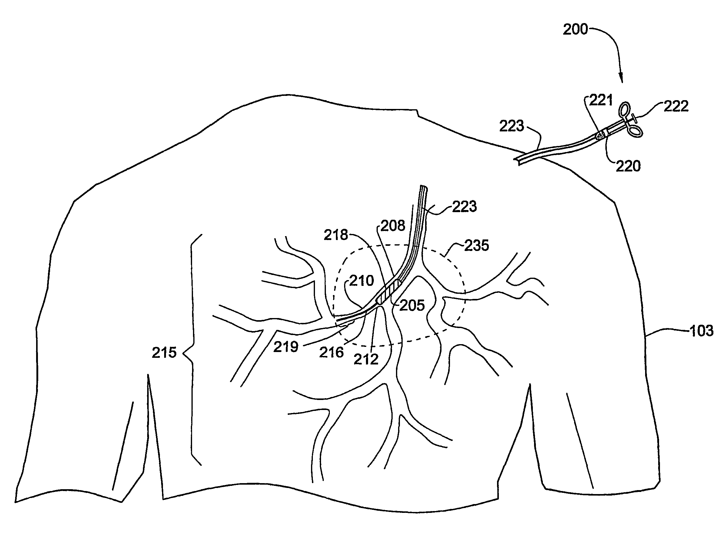
[0041]FIG. 2 shows a catheter 200 the tip 205 of which bas been positioned at an aperture 212 of an artery 210 that is part of an arterial tree 215 of the patient 103. The catheter 200 may be used to deliver an intravascular device ...


PUM


Abstract

A system and method for positioning a device at a desired location in a tubular organ such as an artery. A three-dimensional reconstruction of the organ is obtained, and the desired location is marked in the reconstruction. The device is inserted into the organ and an image is obtained of the device and organ. The reconstruction with the marked location is projected onto a plane from the perspective of the image and the projection and image are superimposed. If the device is not at the desired location, the device is repositioned in the organ and an additional image of the device is obtained. The reconstruction is then projected onto a plane from the perspective of the additional image and the additional image and the projection are superimposed. This process is repeated, as required, until the device is in the desired location.

Description

[0001]The present application claims the benefit of U.S. Provisional Appln. No. 60 / 240,984, filed Oct. 18, 2000.FIELD OF THE INVENTION[0002]The present invention relates to methods of positioning a device in a tubular organ of the body.BACKGROUND OF TIRE INVENTION[0003]Interventional radiology procedures are becoming increasingly important in the treatment of physiological abnormalities such as lumen stenosis or aneurysm. For example, in order to treat a stenotic coronary artery, it is often required to inflate a balloon, apply an atherectomy or thrombectomy device and place a stent (prosthesis) at a diseased artery site. The intravascular device (balloon, stent, atherectomy or thrombectomy device, for example) is usually mounted onto a guide wire and brought to the vessel to be treated using the guide wire and a catheter. When the catheter tip has reached the arterial region to be treated, the guide wire is extended from the catheter tip and is used to position the device inside th...

Claims


Application Information

Patent Timeline
Patent Type & Authority Patents(United States)
IPC IPC(8): A61B5/05A61B6/00A61B6/12
CPCA61B6/12A61B6/481A61B6/504A61B6/5235
Inventor EVRON, RAMICARMELE, RANKLEIMAN, MOSHE
Owner PAIEON INC
Why Eureka
Try Eureka