
Reverse pressure double dam face seal

a face seal and reverse pressure technology, applied in engine seals, non-positive displacement fluid engines, pump components, etc., can solve the problems of small amount of oil to leak past the face seal, odor of oil leaking into the passenger cabin, etc., and achieve the effect of improving drawing clarity

Active Publication Date: 2010-08-24
STEIN SEAL
View PDF38 Cites 19 Cited by
  • Summary
  • Abstract
  • Description
  • Claims
  • Application Information

AI Technical Summary

Benefits of technology

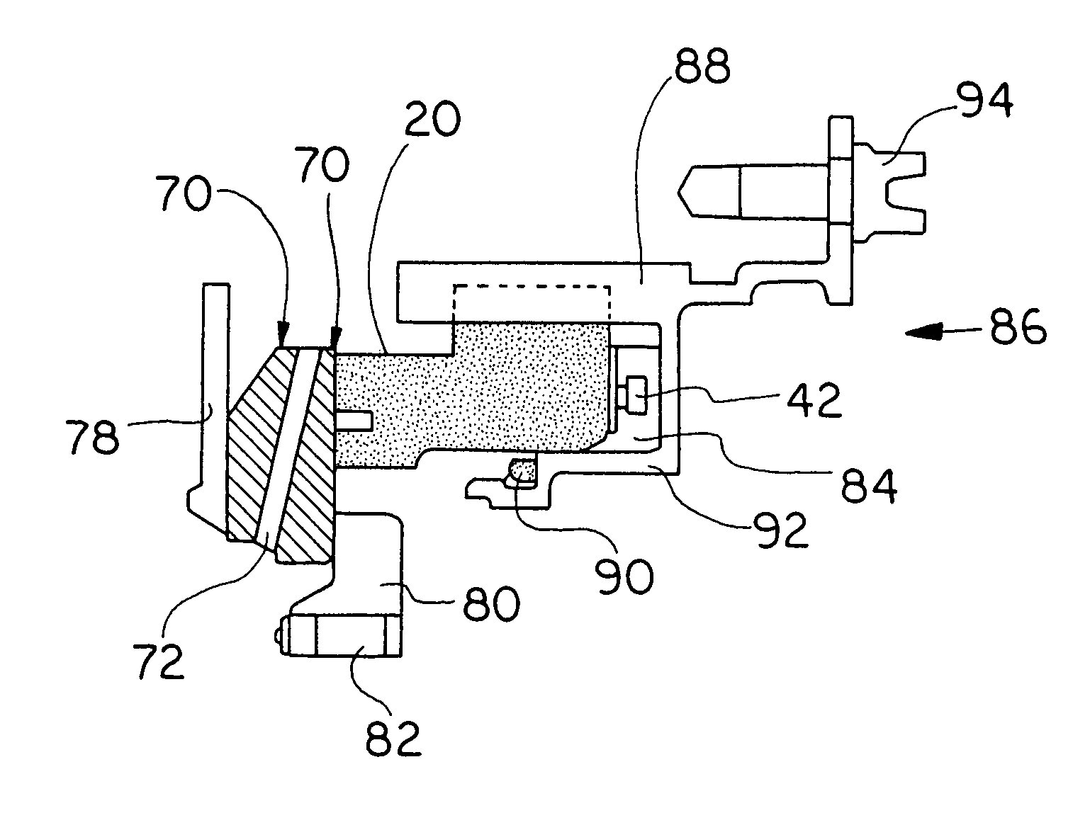
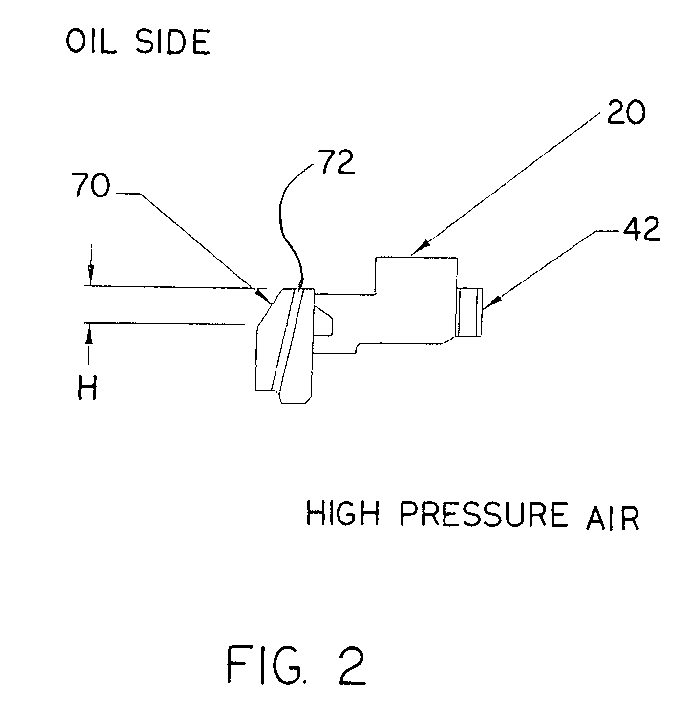
[0013]In yet another of its aspects the invention provides, in the turbomachine described immediately above, a mating ring which further comprises grooves formed on the surface of the ring facingly contacting the stationary member, with the grooves communicating with an inner edge of the mating ring but terminating short of an outer edge of the mating ring, with the grooves being shaped such that a groove outer terminus leads a groove inner terminus during mating ring rotation during normal machine operation, and the grooves overlie and thereby are in fluid communication with the annular channel between the first and second annular sealing dams during normal machine operation. In this aspect of the invention, the grooves overlie the channel, collect air from the air side as the mating ring rotates, and force the air into the channel thereby increasing internal channel pressure to prevent oil leakage into the channel from the lower pressure oil side.
[0016]An alternate approach to this method aspect of the invention further embraces providing grooves in a surface of the mating ring that facingly contacts the first and second face sealing members, with the grooves beginning at and thereby communicating with an interior edge of the mating ring, but terminating short of a the outer edge of the mating ring. The grooves are shaped such that a grove radially inner terminus, at an interior edge of the mating ring, rotatingly leads a groove outer terminus, which is located within the surface of the mating ring and does not communicate with the outer edge of the mating ring, during mating ring rotation in the course of normal machine operation. In this aspect of the invention the mating ring is positioned so that portions of the grooves overlie the annular channel between the first and second face sealing members. As a result, windage resulting from mating ring rotation drives air from the air side and desirably from within the tunnel into and along the grooves for discharge into the annular channel that portions of the grooves overlie, thereby to increase the air pressure in the annular channel above the pressure outboard of the second annular sealing dam defining the outer boundary, pressure wise, of the annular graphite sealing member. With this approach, the relatively higher air pressure in the annular channel prevents oil seepage across the second annular sealing dam since the pressure in the channel is above the pressure of the “oil side” on the outboard side of the second annular sealing dam.

Problems solved by technology

The pressure reversal causes air to flow radially inwardly into the interior chamber or tunnel on the “air side” of the face seal in the engine, causing small amounts of oil to leak past the face seal.
This radially inwardly leaking oil passing the seal, called “oil weepage” in the trade, is deleterious to the engine and, in aircraft engines, may result in the odor of oil leaking into the passenger cabin.

Method used


Image

  • Reverse pressure double dam face seal
  • Reverse pressure double dam face seal
  • Reverse pressure double dam face seal

Examples


Embodiment Construction

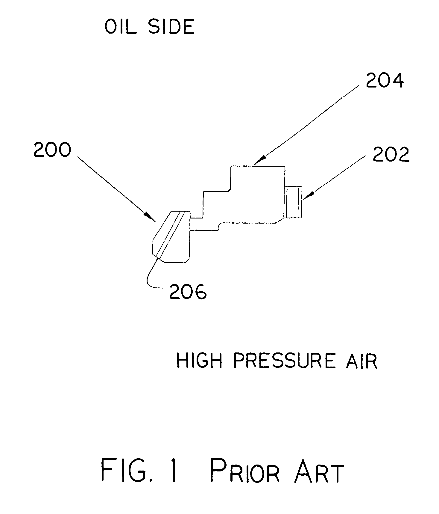
[0030]Referring to the drawings in general and to FIG. 1 in particular, a reverse pressure face seal according to the prior art as illustrated in schematic form in side elevation. The reverse pressure face seal according to the prior art includes a mating ring 200, a wave spring 202 biasing an annular sealing member 204 against mating ring 200. Mating ring 200 is equipped with an oil flow passageway 206 for flow of lubricating, cooling oil from the high pressure side within the turbomachine, indicated by the legend “high pressure air” to the oil mist side within the turbomachine, indicated by the legend “oil side”. Both mating ring 200 and sealing member 204 are annular in the sense that both are of ring-like configuration, with open centers for passage of the high pressure air through the open center of mating ring 200 and the open center of annular sealing member 204. Wave spring 202 biases annular sealing member 204 to the left in FIG. 1, against mating ring 200.

[0031]Referring t...


PUM


Abstract

A double dam reverse pressure face seal assembly for use in the turbomachine having a tunnel extending through the machine for high pressure air passage therein during normal machine operating has a mating ring positioned annularly respecting the tunnel for flow of lubricating oil generally outwardly through passageways in the ring and a sealing member biased against an interface surface of the mating ring, the sealing member including a first dam presenting a first contact face to the interface surface of the mating ring, a second dam integral with an outboard of the first dam, presenting a second contact face to the interface surface of the mating ring and a channel between the first and second dams for annularly downward flow of oil leaking inwardly past the second dam towards a channel exit.

Description

CROSS-REFERENCE TO RELATED PATENT APPLICATION[0001]This patent application claims priority from and the benefit of the filing date of U.S. provisional patent application Ser. No. 60 / 758,408 filed 12 Jan. 2006 in the name of Glenn M. Garrison and entitled “Double Dam Reverse Pressure Face Seal”.BACKGROUND OF THE INVENTION[0002]1. Field of the Invention[0003]This invention relates to reverse pressure face seals for use in jet engines and other turbomachinery to reduce or even to prevent oil weepage through an interface between a seal member and a mating ring when there is a pressure reversal in the sealed chamber or tunnel portion of the engine.[0004]2. Description of the Prior Art[0005]Face seal assemblies for jet engines and other turbomachinery are known and typically include a rotating ring together with a stationary sealing member biased against the ring to prevent leakage therebetween. Lubricating oil typically flows outwardly through generally radial holes in the mating ring, e...

Claims


Application Information

Patent Timeline
Patent Type & Authority Patents(United States)
IPC IPC(8): F04D29/08
CPCF01D25/183F16J15/004F16J15/3416
Inventor GARRISON, GLENN M.
Owner STEIN SEAL
Learn More