Zoom lens assembly and zoom lens module

a technology of zoom lens and zoom lens module, which is applied in the field of optical instrument assembly, can solve the problems of increasing manufacturing costs

Inactive Publication Date: 2010-08-24
ASIA OPTICAL INT LTD
View PDF10 Cites 3 Cited by
  • Summary
  • Abstract
  • Description
  • Claims
  • Application Information

AI Technical Summary

Benefits of technology

[0018]Accordingly, the invention provides a zoom lens assembly and a zoom lens module with reduced components and a small size.
[0022]The first lens and the second lens rotate relatively along the axis to generate zoom effect.
[0030]Thus, by rotating the adjusting tube, the distance between the first lens and the second lens is changed to generate zooming effects.

Problems solved by technology

First, the focusing device 10 requires many components which increases the manufacturing costs.

Method used


Image

  • Zoom lens assembly and zoom lens module
  • Zoom lens assembly and zoom lens module
  • Zoom lens assembly and zoom lens module

Examples


Embodiment Construction

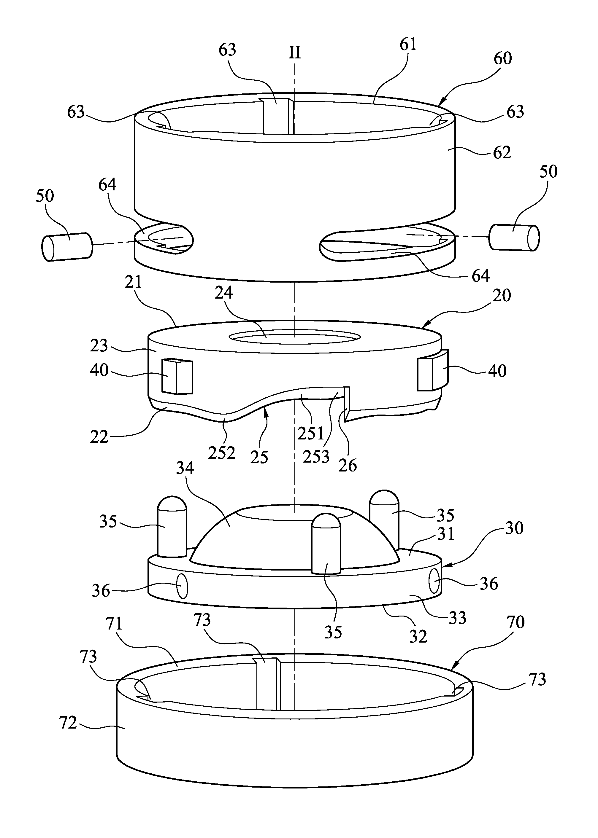
[0042]As shown in FIGS. 3 and 4, the zoom lens assembly or the zoom lens module is assembled to a optical image device (not shown), such as a digital camera, or a projector, to execute focusing functions, which includes zooming and focusing. In a preferred embodiment, the zoom lens module comprises a first lens 20, a second lens 30, a plurality of guiding blocks 40, a plurality of linking members 50, a sheathing tube 60 and a adjusting tube 70.

[0043]The first lens 20 is made by glass molding or plastic injection molding, comprising a first lens surface 21 and a second lens surface 22 opposite to each other along an axis II. A first connecting surface 23 connects the first lens surface 21 and the second lens surface 22. A first effective radius 24 is around the axis II, and a plurality of curved surfaces 25 are disposed on the second lens surface 22 toward the first lens surface 21. A plurality of stop surfaces 26 are between a bottom 253 disposed on the curved surfaces 25 around the...


PUM


Abstract

A zoom lens assembly and zoom lens module are provided, including a first lens, a second lens, a plurality of guiding blocks, a sheathing tube, a plurality of linking members and an adjusting tube. The first lens includes a plurality of curved surfaces disposed on a second lens surface toward a first lens surface. The second lens includes a plurality of driving rods disposed on a third lens surface and abutting the curved surfaces. The guiding blocks are respectively fixed on the first lens. The sheathing tube sheathes the first lens and the second lens and comprises a plurality of guiding notches to receive the guiding blocks, and a plurality of slits. The linking members pass through the slits and are fixed on the second lens. The adjusting tube sheathes the sheathing tube and comprises a plurality of driving notches to receive the linking members.

Description

[0001]This Application claims priority of Taiwan Patent Application No. 097138907, filed on Oct. 9, 2008, the entirety of which is incorporated by reference herein.BACKGROUND OF THE INVENTION[0002]1. Field of the Invention[0003]The invention relates to an optical instrument assembly, and in particular, to a zoom lens assembly and a zoom lens module.[0004]2. Description of the Related Art[0005]As shown in FIGS. 1 and 2, a focusing device 10 often assembled on an optical image device (for example, a camera and a projector) has functions of zooming and focusing. The focusing device 10 has a first frame set 11 along an axis I, a second frame set 12, a fixing tube 13 sheathing the first frame set 11 and the second frame set 12, a first cam tube 14 and a second cam tube 15 sheathing the fixing tube 13, three first driving bolts 16 and three second driving bolts 17.[0006]The first frame set 11 has a through space 111 along the axis I to receive a first lens group (not shown), and three tap...

Claims


Application Information

Patent Timeline
Patent Type & Authority Patents(United States)
IPC IPC(8): G02B15/14G02B7/02
CPCG02B7/10
Inventor LEE, TSU-MENGKUO, HUI-CHUAN
Owner ASIA OPTICAL INT LTD
Why Eureka
Try Eureka