
Wireless communications system, transmitting station, and receiving station

a wireless communication and transmitting station technology, applied in the field of wireless communications systems, can solve the problems of data collision in subsequent time frames, inefficient scheme, and difficulty in appropriating transmitting control

Inactive Publication Date: 2010-08-24
NTT DOCOMO INC
View PDF11 Cites 36 Cited by
  • Summary
  • Abstract
  • Description
  • Claims
  • Application Information

AI Technical Summary

Benefits of technology

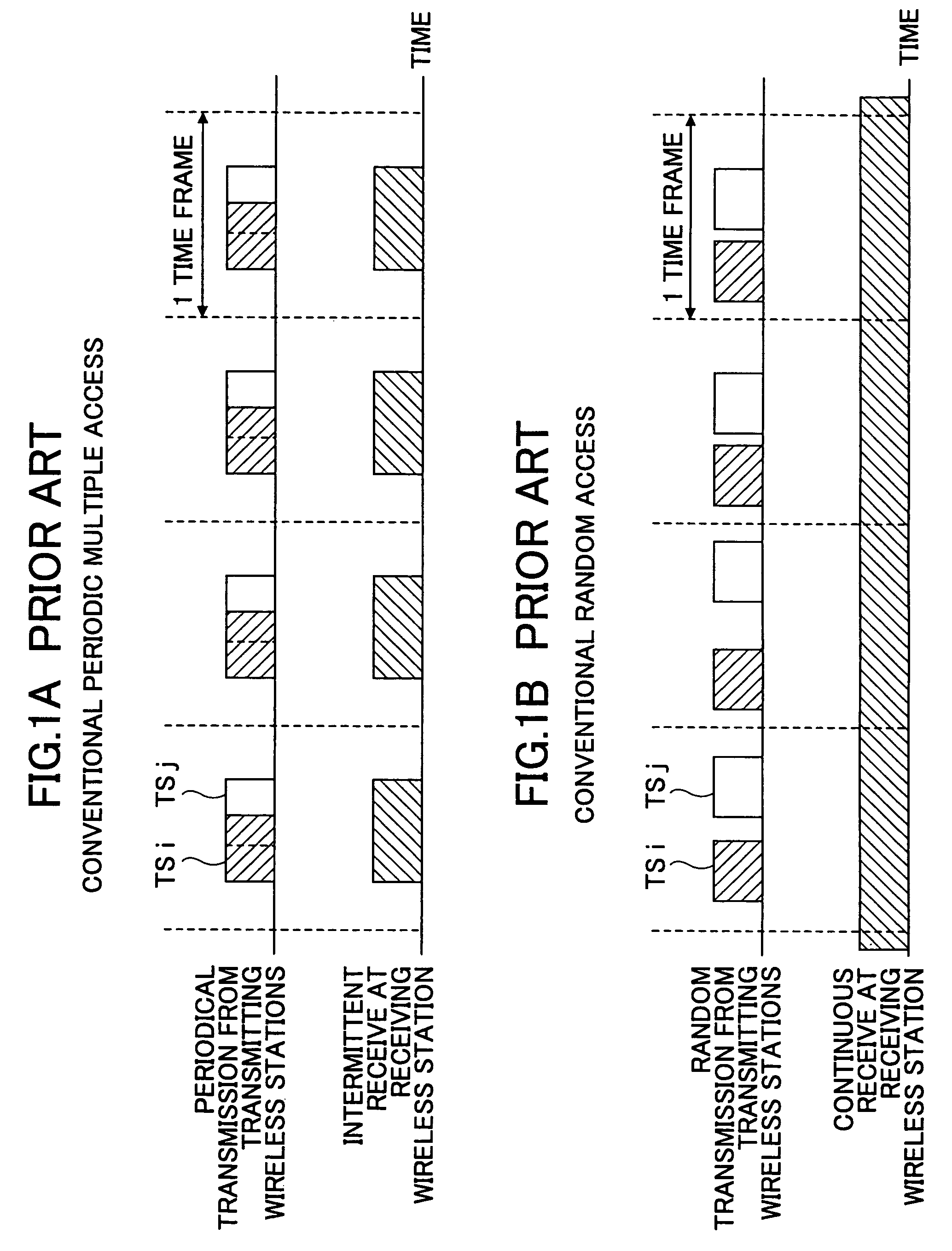
The present invention provides a wireless communications system, a transmitting wireless station, and a receiving wireless station that can prevent data collision and reduce power consumption by allowing the transmitting wireless station to perform random transmission, while allowing the receiving wireless station to perform intermittent receive. The system achieves this by allowing the transmitting wireless station to acquire unique transmit timing sequences based on its unique value or a common value among transmitting stations, and controlling the transmission of information based on the acquired transmit timing sequences. The receiving wireless station extracts the unique value from the received information, acquires the transmit timing sequence of the transmitting station, and synchronizes its receive timing with the transmit timing of the transmitting station. This ensures that data transmission and reception are synchronized, and reduces power consumption.

Problems solved by technology

However, since only a limited number of time slots are available in a single channel, appropriate transmit control becomes difficult under the situation where a number of cellular phones exist.
This scheme is inefficient because of large power consumption.
Accordingly, once data collision occurs, data collision keeps on occurring in the subsequent time frames.
This causes the power consumption to increase.

Method used


Image

  • Wireless communications system, transmitting station, and receiving station
  • Wireless communications system, transmitting station, and receiving station
  • Wireless communications system, transmitting station, and receiving station

Examples


second embodiment

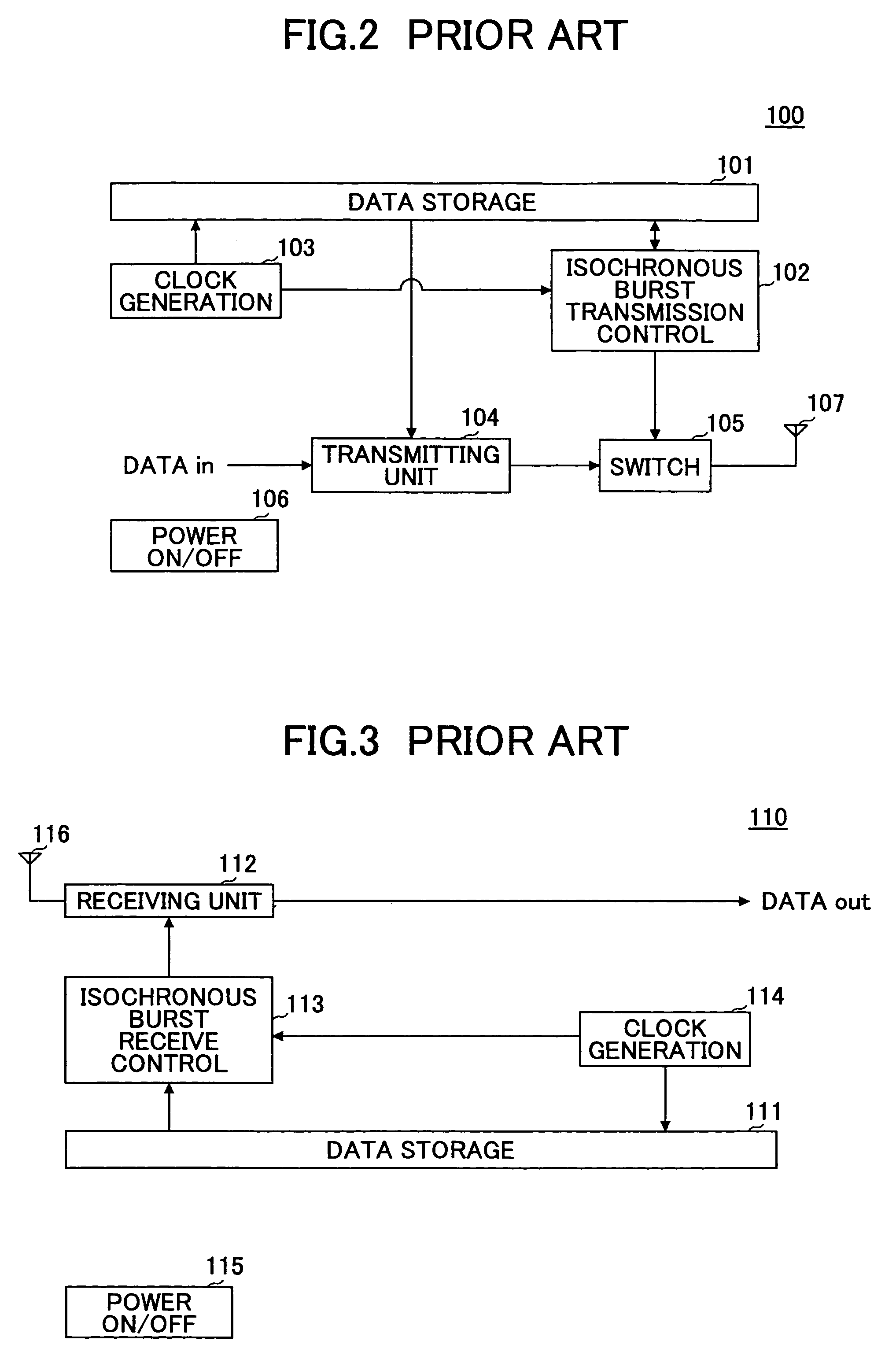
[0092]FIG. 12 is a schematic block diagram of the transmitting wireless station 2000 according to the second embodiment of the invention. The transmitting wireless station 2000 includes a data storage unit 101, a switch 105, a power on / off unit 106, an antenna 107, a burst transmission control unit 1001, a clock generating unit 1002, a transmitting unit 1003, a random value selector 2001, a random sequence estimator 2002, and a transmit timing estimator 2003. The random value selector 2001, the random sequence estimator 2002, and the transmit timing estimator 2003 structure transmit timing sequence acquiring means. The same elements as those shown in FIG. 8 are denoted by the same numerical references, and explanation for them is omitted.

[0093]The data storage unit 101 stores the identification number (ID) of the transmitting wireless station 2000, a transmit timing sequence (Hs), a transmit timing sequence period (Ht), the focused code number (Hn_t) of the transmit timing sequence,...

third embodiment

[0122]FIG. 17 is a schematic block diagram of the transmitting wireless station 2100 according to the third embodiment of the invention. The transmitting wireless station 2100 includes a data storage unit 101, a switch 105, a power on / off unit 106, an antenna 107, and a burst transmission control unit 1001, a clock generating unit 1002, a transmitting unit 1003, a random value selector 2001, a random sequence estimator 2002, a transmit timing estimator 2003, and a data communication control unit 2004. The random value selector 2001, the random sequence estimator 2002 and the transmit timing estimator 2003 structure transmit timing sequence acquiring means. The same elements as those shown in FIG. 12 are denoted by the same numerical references, and explanation for them is omitted.

[0123]The transmitting unit 1003 is connected to the antenna 107 via the switch 105 so as to transmit the identification number (ID) of the transmitting wireless station 2100 and the focused code number (Hn...

fourth embodiment

[0129]FIG. 19 is a schematic block diagram of the transmitting wireless station 3000 according to the fourth embodiment of the invention. The transmitting wireless station 3000 includes a data storage unit 101, a switch 105, a power on / off unit 106, an antenna 107, a transmitting unit 1003, a random value selector 2001, a random sequence estimator 2002, and a transmit timing estimator 2003. The transmitting wireless station 3000 also includes a burst transmit / receive control unit 3001 functioning as transmission control means, a clock generating unit 3002 functioning as phase information correcting means, a reference clock receiving unit 3003, and another antenna 3004. The same elements as those shown in FIG. 12 are denoted by the same numerical references, and explanation for them is omitted.

[0130]The data storage unit 101 stores the identification number (ID) of the transmitting wireless station 3000, a transmit timing sequence (Hs), a transmit timing sequence period (Ht), the foc...


PUM


Abstract

A receiving station used in a wireless communication system receives information from one or more transmitting stations. The receiving station comprises a receiving unit (112) configured to receive information containing ID information of a transmitting station, and a data extracting unit (1011) configured to extract the ID information from the received information. Transmit timing sequence acquiring means (2012, 2013 and 2014) of the receiving station estimates a transmit timing sequence (Hs) of the transmitting station based on the extracted ID information. Synchronizing means (2014) of the receiving station brings the receive timing of the receiving station in synchronization with transmit timing of the transmitting station based on the transmit timing sequence.

Description

BACKGROUND OF THE INVENTION[0001]1. Field of the Invention[0002]The present invention generally relates to a wireless communications system including multiple transmitting stations and a receiving station for receiving information from the transmitting stations, as well as to a communication control technique used in such a wireless communication system.[0003]2. Description of the Related Art[0004]In wireless communications systems (such as mobile communications systems), contention occurs in a channel when multiple transmitting wireless stations have to share the channel to transmit data simultaneously. Accordingly, some access protocol for allocating the channel to each of the transmitting wireless stations is required to prevent data collisions. JP 11-196473A discloses a technique for avoiding collisions that may occur when multiple mobile stations power on at the same time. In this publication, a unique number is assigned to each mobile station. By counting down the number at ea...

Claims


Application Information

Patent Timeline
Patent Type & Authority Patents(United States)
IPC IPC(8): H04B7/00H04B7/204H04B7/26H04B15/00
CPCH04W74/085H04W56/00Y02B60/50Y02D30/70
Inventor TAKIISHI, KOSEIOHKUBO, SHINZOSUDA, HIROHITO
Owner NTT DOCOMO INC
Learn More