Actuator with memory part for building management system

Active Publication Date: 2010-08-24
ZUMTOBEL LIGHTING GMBH & CO KG
View PDF23 Cites 0 Cited by
  • Summary
  • Abstract
  • Description
  • Claims
  • Application Information

AI Technical Summary

Benefits of technology

[0007]The present invention is now based on the object of avoiding the above-described problems in the case of illumination systems or in the case of building management systems in general. Further, a possibility is to be indicated for being better able to monitor the operating condition of an actuator, in order for example to simplify the discovery of causes for possible defects of the device.
[0009]In accordance with a first aspect of the present invention it is proposed to so configure the actuator provided for employment in the building management system, which actuator has a control device which is constituted for the purpose of receiving control commands from the central control unit and to operate the actuator in dependence upon these control commands, and also a memory part for storing function-relevant information, that the memory part is separate or separable from the control device. Through this there is opened up the possibility that the control device of the actuator, thus for example the electronic ballast of a luminaire, can be exchanged separately from the memory part, so that upon an exchange of the control device the new control device can access the information originally contained in the actuator or the luminaire. In contrast to the previously known solutions, upon the replacement of the control device, no complex new programming is needed, since the originally available information can remain as before in the actuator or the luminaire. The not insignificant costs connected with a new programming of the device can thus be avoided by means of the solution in accordance with the invention.
[0010]In a simple variant of the present invention it can be provided that the memory part is fixedly integrated in the actuator, whilst in contrast the control device can be removed separately from the memory part out of the actuator and replaced by a similar new device. Beyond this, however, it would also be conceivable to constitute the memory part also to be exchangeable, which would bring with it further advantages with regard to programming possibilities. Thus, it is usually provided that the first programming of the memory part is effected on production, i.e. before the actuator is commissioned. If however, at a later point in time, an alteration of the programming is undertaken, this can in the case of an exchangeable memory part be effected in simple manner in that the old memory part is replaced by a new part already written with the new operating information. In this case likewise the outlay for new programming of the device can be reduced, since the new memory part with the new data can already be programmed at a central location—for example at the producer of the actuators or the company responsible for the illumination or building management system—and then placed in simple manner in the corresponding actuator.
[0014]The above-mentioned concept of regularly detecting operating data of an actuator and storing it in a non-volatile memory, represents a second aspect of the present invention, which can be put to use independently of whether the memory can or cannot be separated from the control part. Through the regular recording of operating data in the sense of a “log” there is the possibility, also after a possible failure of the device, to obtain more detailed information on the previous operation and possibly to determine the cause of the failure of the device. Also maintenance work is significantly simplified in this manner, since for example after reading out of the information stored in the memory it can be determined whether a certain operating time has been exceeded and correspondingly whether possibly an exchange of the device should be considered. Further, there can be determined in simple manner those devices which e.g. operate a light source associated therewith outside permissible operating parameters and correspondingly should be serviced (e.g. newly calibrated) or even replaced. Here it is significant that the device self-actingly undertakes the storing of the operating data and thus self-actingly creates a log of the operation, whereby the data collected in this way can then be read out for maintenance purposes.
[0016]Through this second aspect in accordance with the invention, thus in particular the possibilities for monitoring the operation of the actuator, and therewith for determining possible fault conditions, are improved.

Problems solved by technology

By means of the above-described measure of programming it can be ensured that the ballast can be put to use in different luminaires and suitably control different lamp types, but problems can arise from the fact that the working life and reliability of the mechanical elements of the luminaire in part is significantly higher than that of the ballast.
In other words, it can indeed occur that in the course of the working life of a luminaire the ballast must be exchanged due to a defect or other manifestations of wear.
In this case, however, the information programmed into the original ballast on production, is lost.
A similar problem to that described above arises in general in the case of so-called building management systems, with which a plurality of so-called actuators, arranged in a distributed manner, are controlled from a central control unit.
These problems may make themselves noticeable as delays and cost overruns in the necessary first programming of the installation.
Beyond this, a subsequent function alteration or extension of the installation is associated with in part very high programming costs.
Finally, analogously to the above-indicated case, the exchange of a defective ballast gives rise to the problem that in the case of a device failure and the employment of a corresponding replacement device the originally programmed information is lost and correspondingly a new programming is needed, through which high additional costs arise.
A further problem of these modern actuators consists finally also in that, due to the multiplicity of functions and operating possibilities of these devices, the most varied causes for a possible defect come into question.
Thus, a failure of a lamp operating device can for example be due to operation of the light source within a critical operating parameter region; however, it could also simply be the case that the intended operational life of the device or of the light source has in the meantime been exceeded.
If now a lamp operating device or in general an actuator in fact fails, it is thus often very difficult to determine the actual cause of the failure and—so far as possible—possibly to take measures to avoid such difficulties in future.

Method used


Image

  • Actuator with memory part for building management system
  • Actuator with memory part for building management system
  • Actuator with memory part for building management system

Examples


Embodiment Construction

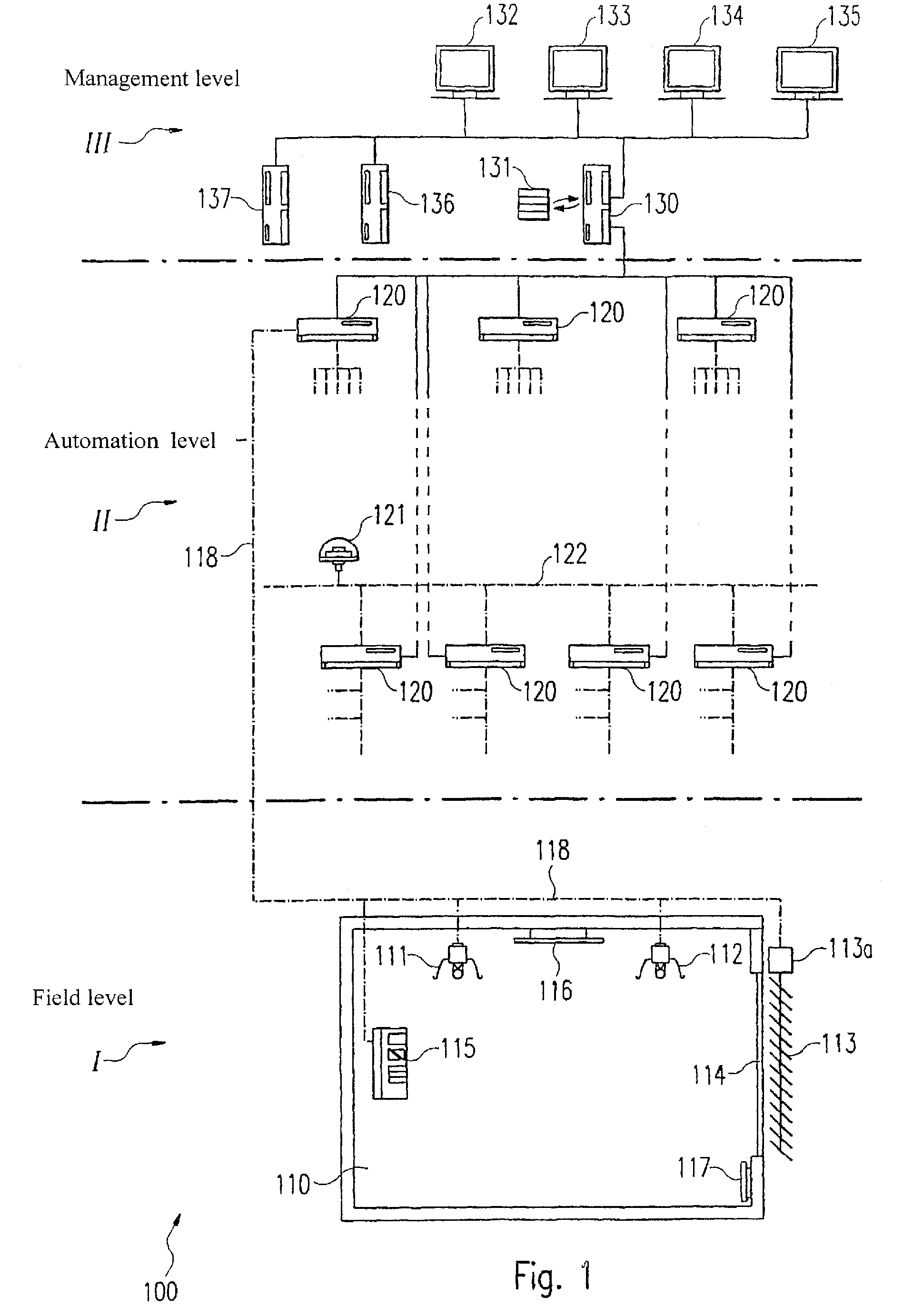
[0023]Before the configuration and manner of functioning of actuators configured in accordance with the invention is described in more detail, first the configuration of a more complex building management system will be explained with reference to FIG. 1. Thereby, FIG. 1 shows a more complex building management system which is provided for the control of a plurality of actuators within a larger building.

[0024]The building management system represented in FIG. 1 and provided overall with the reference sign 100, seen hierarchically, can be divided into three levels. Here there are involved in increasing sequence, the so-called field level I, the automation level II, and the management level III. The three levels thereby differ with regard to the devices therein and their manner of functioning, which is to be explained below.

[0025]In the lowest so-called field level I, there are located first primarily the actuators and the operating elements. The actuators may be for example the lumin...


PUM


Abstract

A building management system (1) for the control of plural actuators (10) arranged in a distributed manner, comprised of a central control unit (2) and at least one actuator (10) controlled by the central control unit (2), wherein the actuator (10) has a control device (11) which is formed to receive control commands from the central control unit (2) and to operate the actuator (10) in dependence upon these control commands, and a memory part (13) for storing function-relevant information. In accordance with the invention the memory part (13) is separate or separable from the control device (11).

Description

FIELD OF THE INVENTION[0001]The present invention relates to a building management system for the control of a plurality of actuators arranged in the distributed manner, and an actuator which is provided for employment in a corresponding building management system and has a memory part for storing function-relevant information. In particular the present invention relates to an illumination system having a central control unit for the control of a plurality of luminaires arranged in a distributed manner, and a corresponding luminaire.BACKGROUND OF THE INVENTION[0002]Electronic ballasts for operating lamps, in particular gas discharge lamps, are usually so configured that they can be employed for the control of different lamp types and can be put to use in different luminaire types. Correspondingly, electronic ballasts are produced in very great numbers and at the end of their production process are installed in a luminaire, so that the mechanism of the luminaire and the electronics, ...

Claims


Application Information

Patent Timeline
IPC IPC(8): G05B21/00G05D23/00G05B15/00G05B23/00G01M1/38G05B19/18G05B11/01G05B15/02G05B23/02G09G1/28H01J25/50G09G1/04H02J13/00H05B37/02
CPCH05B37/0245H05B47/175
Inventor JAHN, GERHARDFA, JOSEF
Owner ZUMTOBEL LIGHTING GMBH & CO KG
Why Eureka
Try Eureka