Power storage equipment management system

a technology for power storage equipment and management systems, applied in non-electric variable control, process and machine control, instruments, etc., can solve the problems of increasing power consumption, increasing the average amount of power consumption each year, and inability to efficiently operate power generation equipment, etc., to achieve the effect of promoting the introduction of such equipmen

Inactive Publication Date: 2010-08-24
SHARP KK
View PDF23 Cites 162 Cited by
  • Summary
  • Abstract
  • Description
  • Claims
  • Application Information

AI Technical Summary

Problems solved by technology

Therefore, the amount of power consumption is growing each year.
Further, the load factor which is a ratio between the amount of power consumption at the peak time and the average amount of power consumption is getting worse each year.
The worsening in the load factor requires power companies to maintain power generation equipment for coping with the peak power demand, which causes a problem that they cannot operate the power generation equipment efficiently.
However, it is not a system giving values by evaluating a value for the environmental contribution in addition to an economical value obtained by storing power in power storage equipment and consuming the power.
In general, power storage equipment for storing power is not widely used currently due to the high installment cost and maintenance cost.
Although there is a problem that the load factor worsens as described above, no system exists for grasping and evaluating situations about values of power usage patterns in which power storage equipment and power generation equipment affect the improvement of the load factor.
Further, it is impossible to actually classify the types of power.
Consequently, the fact that sufficient economical benefit cannot be gained in many cases is considered as one reason of hampering widespread of power storage equipment.
Further, although power generation equipment placing small environmental load may be widespread further in the future, the power generation cost including the introduction cost has not reached the same level as the power generation cost of the electric power company performing power generation with large-scale power generation equipment.
In particular, there is no means to evaluate environmental contribution by a user, having small-scale power storage equipment such as one for a household use, who stores midnight power and uses it in the daytime so as to level the load whereby carbon dioxide generated when generating power can be reduced, or to evaluate environmental contribution by self-consuming power generated by small-scale power generation equipment so as to contribute to the load leveling of a large-scale power generation plant.
Further, since the contribution is small in the absolute amount when taken individually, there is no system for collecting them on which a third party who wants to obtain the values depends.
Therefore, it is impossible to distribute the values.
For example, it is impossible to make a transaction (selling) of the values like carbon dioxide emission right.

Method used


Image

  • Power storage equipment management system
  • Power storage equipment management system
  • Power storage equipment management system

Examples


first embodiment

[0057]Hereinafter, the present invention will be explained in detail based on an embodiment. Note that the present invention is not limited to this embodiment.

(Configuration of Power Storage Equipment Management System)

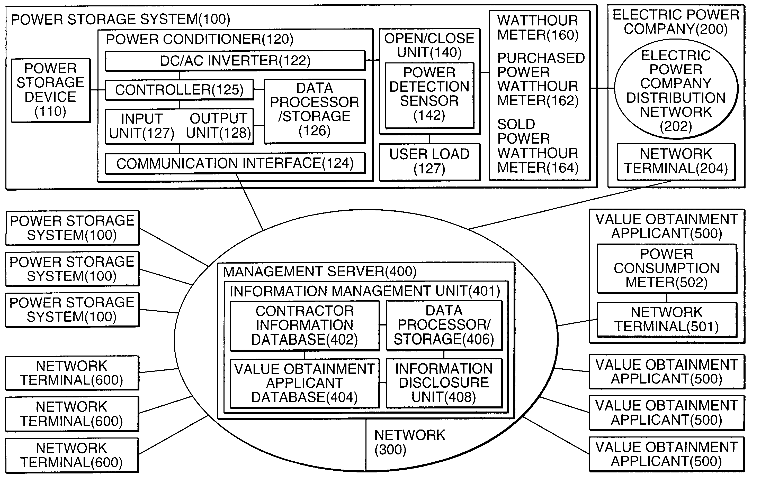
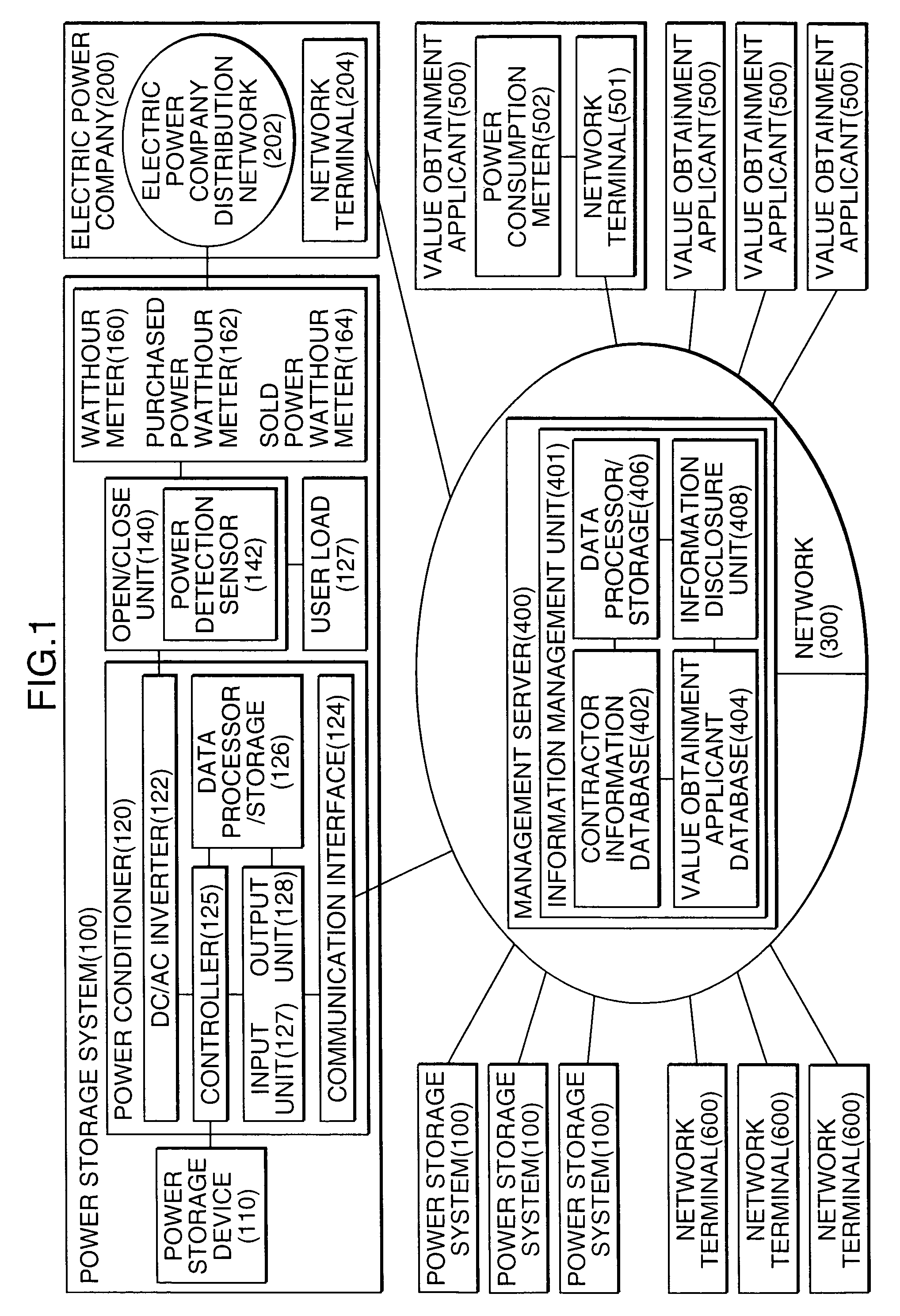
[0058]FIG. 1 shows a block diagram of an overall configuration of a power storage equipment management system according to the present technology.

[0059]The power storage equipment management system of the present technology mainly has a power storage system 100 and a management server 400, and includes, as required: a network terminal 204, held by an electric power company 200, for linking with the power storage management system of an example embodiment; a network terminal 501, held by a value obtainment applicant 500, for linking with the power storage management system an example embodiment; and a network terminal 600, held by the owner or a manager of the power storage system 100, for linking with the power storage management system of the example embodiment and f...

second embodiment

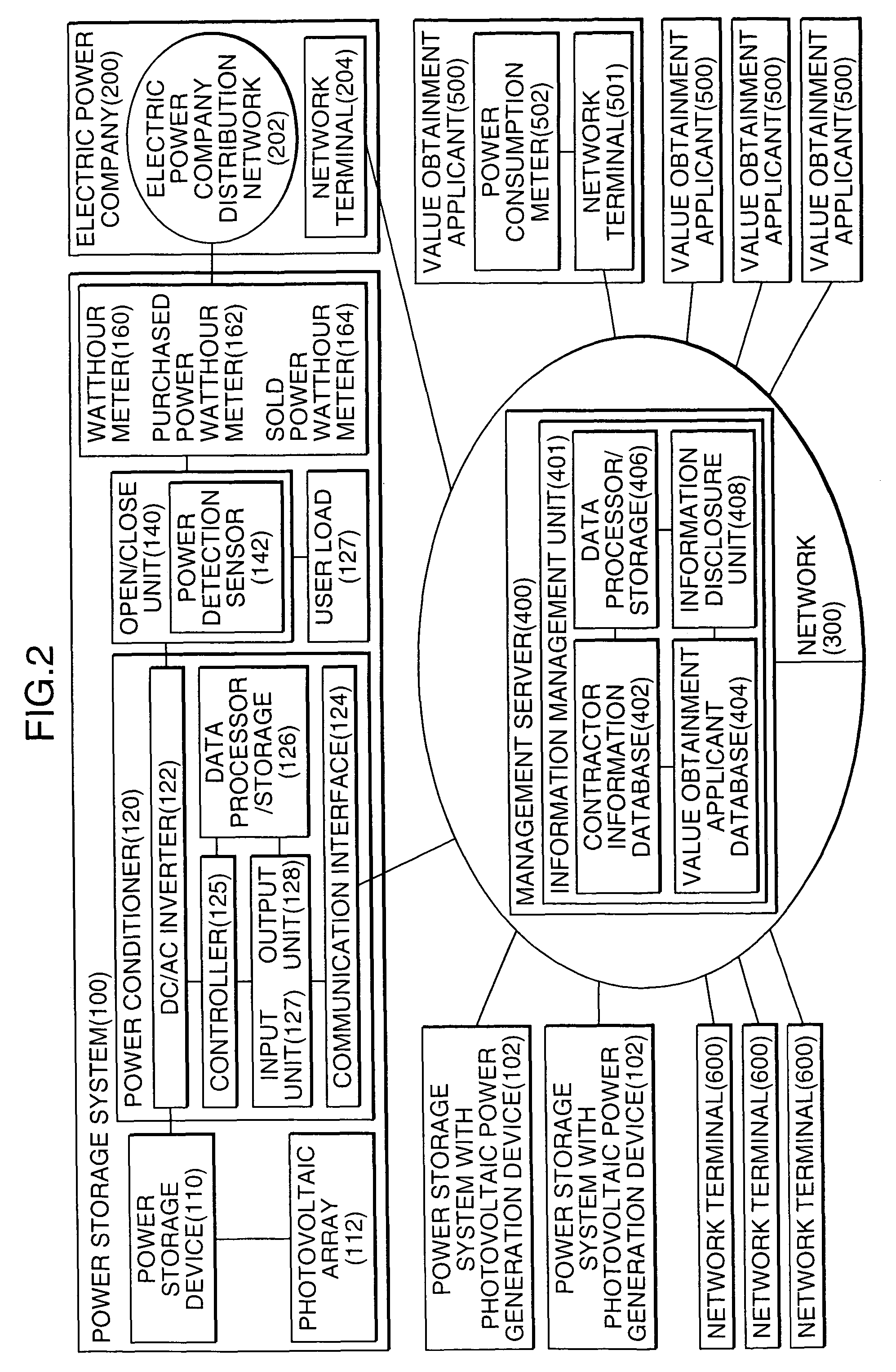
[0122]Next, explanation will be given for a specific example of an embodiment in which a contractor selects any one of considerations when there are a plurality of considerations. Here, explanation will be given with reference to the example of the power storage system provided together with photovoltaic power generation device shown in FIG. 2. Basic configuration, operation and flowchart are same as those of the first embodiment. In the present system, generated power information which is generated by using the photovoltaic power generation device is added. As for the generated power information, it is considered that a high value may be set when power is generated by using a solar cells in the daytime in midsummer and is provided by reverse flow to the user load or to the system. In a case where the power generation equipment and the power storage system are installed together as described above, it is possible to handle by converting to points which have been set beforehand in or...

third embodiment

(Mutual Services with Services of Different Industries)

[0154]Systems for acquiring goods or converting to money by mileage services and point systems intended for attracting users are widely spread among credit card companies, airline companies and various stores. A specific example of a mutual service with such a service will be explained.

[0155]In this case, based on each value information, power amount obtained from power information must be converted into points or the like so as to be treated in a common unit. Hereinafter, a mutual service with a credit card company will be explained.

Point Criteria

[0156]1 kWh=2 points

[0157]When power is generated by photovoltaic power generation and consumed in a time period from 12 o'clock to 16 o'clock (including time shift by storage battery).

[0158]When power is generated by a fuel cell having a cogeneration system and consumed in a time period from 12 o'clock to 16 o'clock (including time shift by storage battery).

[0159]1 kWh=1 point

[0160]Wh...


PUM


Abstract

A power storage equipment management system has a power storage equipment, and a management server for managing power information of the power storage equipment. The power storage equipment includes a power receiving unit for obtaining power for charging, a power supplying unit for supplying charged power to a load, an information controller for generating power information by charging and discharging of the power receiving unit or the power supplying unit, and a communication unit for transmitting the power information to the management server. The management server includes an information management unit for determining a consideration with respect to the power information transmitted from the power storage equipment by using consideration information which has been set beforehand.

Description

CROSS-REFERENCE TO RELATED APPLICATION[0001]This application is related to Japanese Patent Application No. 2004-351325 filed on Dec. 3, 2004, on the basis of which priority is claimed under 35 USC §119, the disclosure of this application being incorporated by reference in its entirety.BACKGROUND OF THE INVENTION[0002]1. Field of the Technology[0003]The present technology relates to a management system for power storage equipment which stores power, or a management system for power storage equipment provided together with power generation equipment. In particular, the present technology relates to a system enabling to expand user's merits so as to promote introduction of power storage equipment by establishing such a system that a user who installs power storage equipment is provided with not only economical values obtained by storing power in the power storage equipment and consuming it, but also social status and values for the environmental contribution.[0004]The present technolog...

Claims


Application Information

Patent Timeline
Patent Type & Authority Patents(United States)
IPC IPC(8): G05D3/12H02J3/00G06Q50/00G06Q50/06H02J3/28
CPCG06Q10/087Y04S10/56Y04S10/50
Inventor YAMADA, KAZUOFUKUSHIMA, TAKASHI
Owner SHARP KK
Why Eureka
Try Eureka