
Branch target address cache

a target address and cache technology, applied in the field of data processing, can solve problems such as wasting power dissipation, reducing performance, and creating significant performance penalties, and achieve the effect of improving the branch target address cach

Inactive Publication Date: 2010-08-24
IBM CORP
View PDF10 Cites 28 Cited by
  • Summary
  • Abstract
  • Description
  • Claims
  • Application Information

AI Technical Summary

Benefits of technology

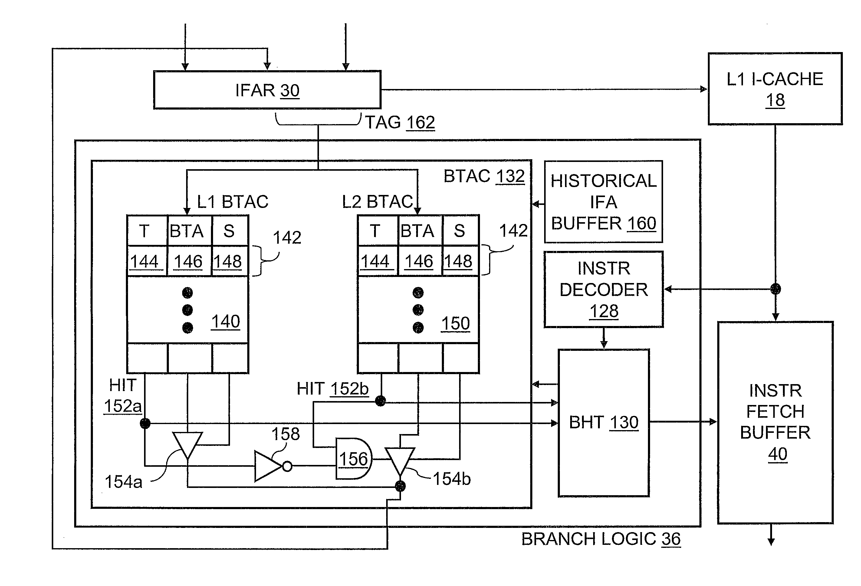
The present invention is a data processing system that uses an enhanced branch target address cache to improve performance. The system includes a processor with an execution unit and instruction sequencing logic that fetches instructions from memory. The instruction sequencing logic includes branch logic that predicts branch target addresses and accesses a level one and level two cache in parallel to obtain predicted branch target addresses for use as instruction fetch addresses. The system improves data processing speed and efficiency by accessing the cache in parallel, reducing processing cycles and improving overall performance.

Problems solved by technology

Unresolved conditional branches, on the other hand, can create significant performance penalties if fetching of sequential instructions is delayed until the condition upon which the branch depends becomes available and the branch is resolved.
During the several cycles required for the instruction fetch, branch scan, and instruction fetch redirect, instructions continue to be fetched along the not taken path; in the case of a predicted-taken branch, the instructions within the predicted-taken path are discarded, resulting in decreased performance and wasted power dissipation.
However, in conventional designs, the BTAC access still generally requires multiple cycles, meaning that in the case of a BTAC hit at least one cycle elapses before the taken branch redirect.
Unfortunately, this interval tends to grow as processors achieve higher and higher operating frequencies and as BTAC sizes increase in response to the larger total number of instructions (i.e., “instruction footprint”) of newer software applications.

Method used


Image

  • Branch target address cache
  • Branch target address cache
  • Branch target address cache

Examples


Embodiment Construction

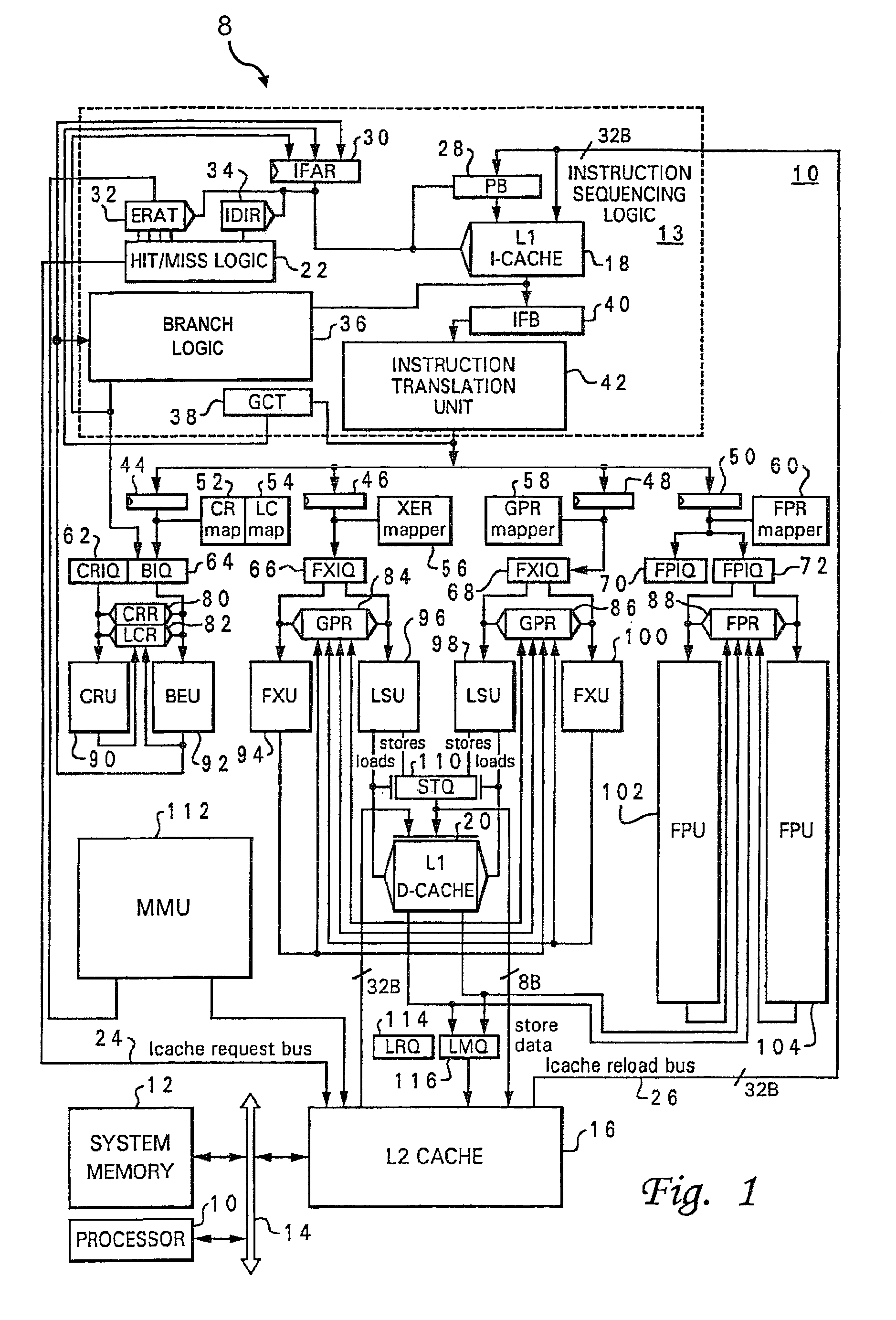
[0021]With reference now to FIG. 1, there is illustrated a high level block diagram of an exemplary data processing system 8 in accordance with the present invention. As shown, data processing system 8 includes a processor 10 comprising a single integrated circuit superscalar processor, which, as discussed further below, includes various execution units, registers, buffers, memories, and other functional units that are all formed by integrated circuitry. Processor 10 may be coupled to other devices, such as a system memory 12 and a second processor 10, by an interconnect fabric 14 to form a data processing system 8 such as a workstation or server computer system. Processor 10 also includes an on-chip multi-level cache hierarchy including a unified level two (L2) cache 16 and bifurcated level one (L1) instruction (I) and data (D) caches 18 and 20, respectively. As is well known to those skilled in the art, caches 16, 18 and 20 provide low latency access to cache lines corresponding t...


PUM


Abstract

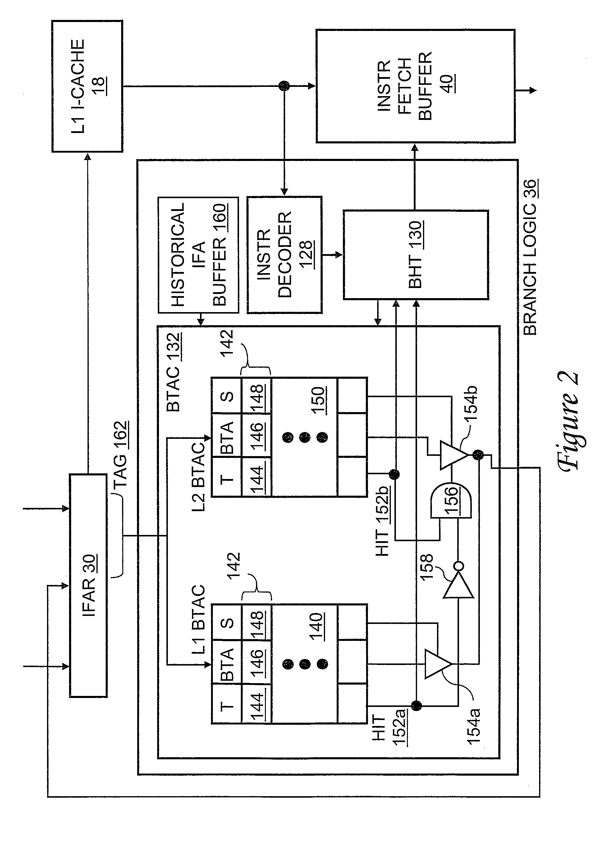
A processor includes an execution unit and instruction sequencing logic that fetches instructions from a memory system for execution. The instruction sequencing logic includes branch logic that outputs predicted branch target addresses for use as instruction fetch addresses. The branch logic includes a level one branch target address cache (BTAC) and a level two BTAC each having a respective plurality of entries each associating at least a tag with a predicted branch target address. The branch logic accesses the level one and level two BTACs in parallel with a tag portion of a first instruction fetch address to obtain a first predicted branch target address from the level one BTAC for use as a second instruction fetch address in a first processor clock cycle and a second predicted branch target address from the level two BTAC for use as a third instruction fetch address in a later second processor clock cycle.

Description

BACKGROUND OF THE INVENTION[0001]1. Technical Field[0002]The present invention relates in general to data processing and, in particular, to branch prediction. Still more particularly, the present invention relates to a data processing system, processor and method of data processing with an improved branch target address cache (BTAC).[0003]2. Description of the Related Art[0004]A state-of-the-art microprocessor can comprise, for example, a cache for storing instructions and data, an instruction sequencing unit for fetching instructions from the cache, ordering the fetched instructions, and dispatching the fetched instructions for execution, one or more sequential instruction execution units for processing sequential instructions, and a branch processing unit (BPU) for processing branch instructions.[0005]Branch instructions processed by the BPU can be classified as either conditional or unconditional branch instructions. Unconditional branch instructions are branch instructions that ...

Claims


Application Information

Patent Timeline
Patent Type & Authority Patents(United States)
IPC IPC(8): G06F9/38G06F9/32
CPCG06F9/3804G06F9/3844G06F9/3806G06F9/3848
Inventor LEVITAN, DAVID S.SPEIGHT, WILLIAM E.ZHANG, LIXIN
Owner IBM CORP
Learn More