Rescue terminal structure

a terminal structure and terminal technology, applied in the direction of emergency protective devices, transportation and packaging, electric/fluid circuit, etc., can solve the problems of unable to stably and safely supply electric power, and the booster cable might be pulled

Active Publication Date: 2010-08-31
YAZAKI CORP
View PDF32 Cites 27 Cited by
  • Summary
  • Abstract
  • Description
  • Claims
  • Application Information

AI Technical Summary

Benefits of technology

[0011]In view of the above-identified problem, an object of the present invention is to provide a rescue terminal structure that allows the clamping portion of the booster cable to be firmly connected to the rescue terminal of the bus bar.
[0013]With the construction and arrangement described above, the ribs are provided on one surface of the supporting plate, and the rescue terminal is positioned on the other (opposite) surface of the terminal supporting plate. Accordingly, the clamping portion of the booster cable for emergency power supply clamps both the rescue terminal and the ribs at one time, and the edge-shaped end and the sawtooth-like teeth of the clamping portion bite into the elongated rib or ribs so that the clamping portion is firmly secured with a large frictional force to the rescue terminal of the bus bar which is connected to the battery. When the driver or an operator is in a hurry to connect the clamping portion to the rescue terminal, or when a pulling force acts upon the clamping portion after the booster cable is connected, the clamping portion is prevented from being displaced or detached from the rescue terminal and thus the electric power can be safely and stably supplied.
[0014]Preferably, the plurality of ribs are parallel to each other. When the clamping portion of the booster cable clamps the rib along a length thereof, the plurality (if not all) of ribs are at one time clamped by the clamping portion of the booster cable (more specifically, by the edge-shaped ends of the clamping portion) and the edge-shaped ends bite into the ribs. Even when the pulling force acts upon the booster cable, the end of the clamping portion is in contact with the rib with a frictional force larger than the pulling force. Accordingly, undesirable displacement and detachment are prevented and electrical power can be supplied more safely and stably. The edge-shaped end of the clamping portion bites into the rib when the clamping portion of the booster cable is attached to the terminal supporting plate from above.
[0015]Preferably, a thickness of the rib is such that the rib is placed under compressive deformation when the rescue terminal and the rib are clamped by the clamping portion, so that the clamping portion of the booster cable bites into the rib to generate large frictional force and the displacement and detachment of the clamping portion form the rescue terminal is effectively prevented.
[0016]Preferably, the body of the fuse block has a hole for inserting the rescue terminal therethrough and allowing the rescue terminal to be provided along the other surface of the terminal supporting plate. By virtue of the hole, the bus bar is accommodated in the block body and at the same time the rescue terminal is allowed to be exposed via the hole to an outside with the rescue terminal slidably and smoothly placed on the other surface of the terminal supporting plate. The hole is a slit slightly larger than a cross-section of the plate-shaped rescue terminal. The hole defines the position of and supports the rescue terminal. Thus, arrangement of the rescue terminal is facilitated.
[0018]With the construction and arrangement described above, electrical junction box, which is constituted for example by a body of the fuse block, the bus bar, the frame, and the fuses mounted to the body of the fuse block. It is preferable that a cover is mounted to the frame and the inner cover resides inside of the cover. Also, it is preferable that other blocks, units, and components other than the body of the fuse block are accommodated together in the frame. In a state where the terminal supporting plate and the rescue terminal are in contact with each other in the thickness direction, the rescue terminal is passed through and supported by the opening of the frame so as to be exposed via the frame to an outside. The inner cover of the frame serves to protect the rescue terminal and isolate the rescue terminal from other components of the electrical junction box. Connection of the booster cable to the rescue terminal is done with the inner cover opened. By a region around the opening of the frame, the rescue terminal is isolated from electrical components such as a fuse and a connector on the side of the block body, and the fuse and connector on the side of the block body is protected against adverse effect that might be caused by connecting the booster cable to the rescue terminal.

Problems solved by technology

When the battery is dead, the driver might be in a hurry to connect the booster cable to the rescue terminal.
Also, it can happen that the booster cable might be pulled.
In such cases, the clamping portion might be inadvertently detached from the rescue terminal, failing to stably and safely supply electric power to the battery waiting for revival.

Method used


Image

  • Rescue terminal structure
  • Rescue terminal structure
  • Rescue terminal structure

Examples


Embodiment Construction

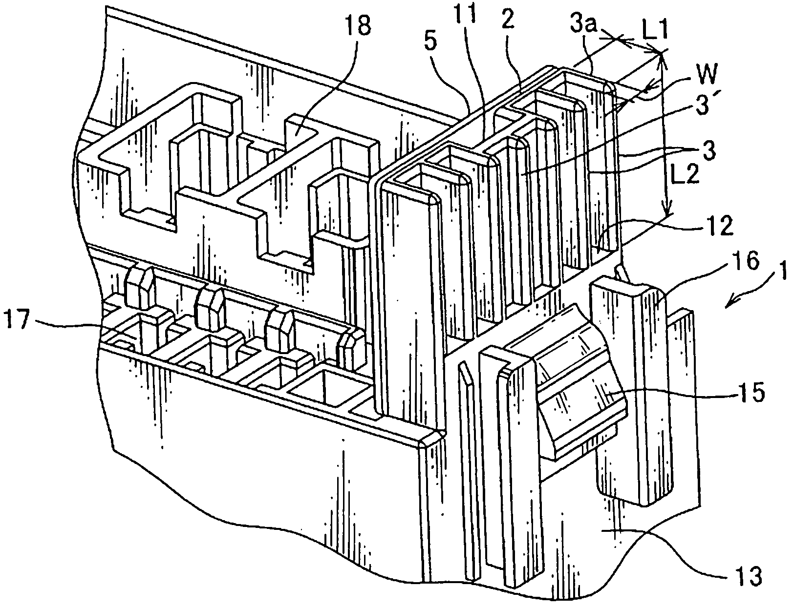
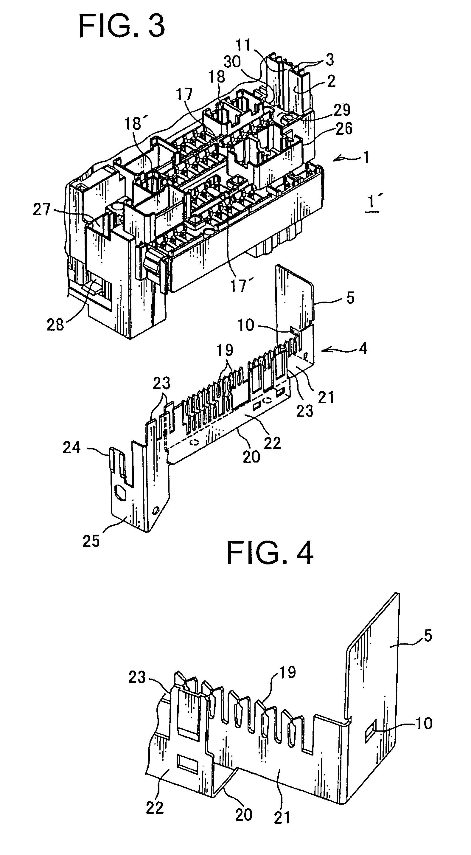
[0027]A rescue terminal structure according to one embodiment of the present invention is described below with reference to FIGS. 1 to 5.

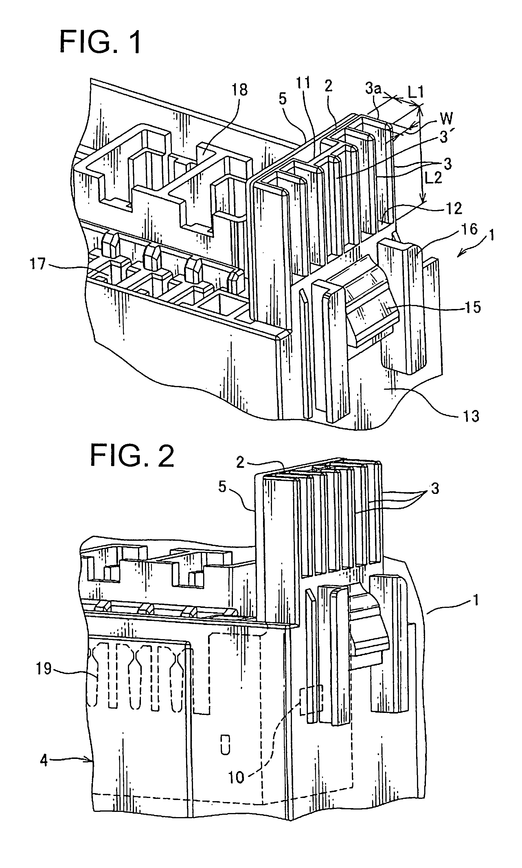
[0028]Referring to FIG. 1, the rescue terminal structure includes three constituent parts, i.e., a terminal supporting plate 2, a plurality of ribs 3, and a rescue terminal 5.

[0029]The terminal supporting plate 2 is formed in one piece with a body of a fuse block made of insulating synthetic resin (block body 1 or junction box body). The terminal supporting plate 2 has the plurality of elongated vertical ribs 3 extending parallel to each other and each upstanding on the outer surface of the terminal supporting plate 2.

[0030]The bus bar has the rescue terminal 5 in a shape of a flat vertical plate. The bus bar 4 is made of electrically conductive metal (see FIG. 2). The rescue terminal 5 is arranged along and in contact with an inner surface of the terminal supporting plate 2 (i.e., a surface opposite the above-mentioned outer surface on which the r...


PUM


Abstract

A block body made of insulating synthetic resin having a terminal supporting plate in one piece therewith. A plurality of elongated ribs project on one surface of the terminal supporting plate and a rescue terminal is arranged on the other surface of the terminal supporting plate. A bus bar is mounted in the block body. A clamping portion of a booster cable can grasp both the rescue terminal and the rib at one time. The plurality of ribs are parallel to each other. The dimension of the rib is defined such that the rib is placed under compressive deformation when the rib is clamped by the clamping portion. The block body has a hole through which the rescue terminal is passed such that the rescue terminal extends along and in contact with the other surface of the terminal supporting plate.

Description

CROSS REFERENCE TO RELATED APPLICATION[0001]The priority application Japan Patent Application No. 2008-097416 upon which this patent application is based is hereby incorporated by reference.BACKGROUND OF THE INVENTION[0002]1. Field of the Invention[0003]The present invention relates to a rescue terminal structure for use in supplying electrical power to a vehicle by connecting a booster cable to a rescue terminal of for example an electrical junction box when a battery of the vehicle is dead.[0004]2. Description of the Related Art[0005]FIG. 6 shows a conventional rescue terminal structure (for example, see FIGS. 1 to 4 of Japanese Patent Application Laid-Open Publication No. 2004-134215).[0006]The conventional rescue structure has a bus bar 52 provided on the plate-shaped block body 51 made of insulating synthetic resin and a rescue terminal 53 upstanding from the bus bar 52. A bolt 55 on the side of the block body 51 is passed through a hole 54 of the bus bar 52. An electrical wire...

Claims


Application Information

Patent Timeline
Patent Type & Authority Patents(United States)
IPC IPC(8): H01R12/00
CPCH01H85/20B60R16/0238
Inventor AKAHORI, MASAHIRONOGAKI, TAKAOIWAI, TOSHINORI
Owner YAZAKI CORP
Why Eureka
Try Eureka