Liquid crystal display device and driving method of the same

a technology of liquid crystal display and driving method, which is applied in the direction of electric digital data processing, instruments, computing, etc., can solve the problems of black display quality being sacrificed, the use efficiency of light is remarkably impaired, and the black display quality in a video signal in which white and black are mixed in a selected line is sacrificed. , to achieve the effect of not sacrificering black display quality

Inactive Publication Date: 2010-08-31
JAPAN DISPLAY CENTRAL CO LTD
View PDF5 Cites 1 Cited by
  • Summary
  • Abstract
  • Description
  • Claims
  • Application Information

AI Technical Summary

Problems solved by technology

Accordingly, in the case where it is necessary to set the reverse transition prevention voltage to be higher than the optimum black display voltage, there is a problem that black display quality must be sacrificed.
However, in such a case, since the display time ratio (display time occupied in the frame period) is reduced, or the white brightness is reduced, there is a problem that the use efficiency of light is remarkably impaired.
However, in the method of JP-A-2003-279931, there remains a problem that the black display quality in a video signal in which white and black are mixed in a selected line is sacrificed.

Method used


Image

  • Liquid crystal display device and driving method of the same
  • Liquid crystal display device and driving method of the same
  • Liquid crystal display device and driving method of the same

Examples


first embodiment

[0025]Hereinafter, a liquid crystal display device 10 of a first embodiment of the invention will be described with reference to FIG. 3 to FIG. 8. The liquid crystal display device 10 of this embodiment is an OCB type normally white liquid crystal display device.

(1) Structure of the Liquid Crystal Display Device 10

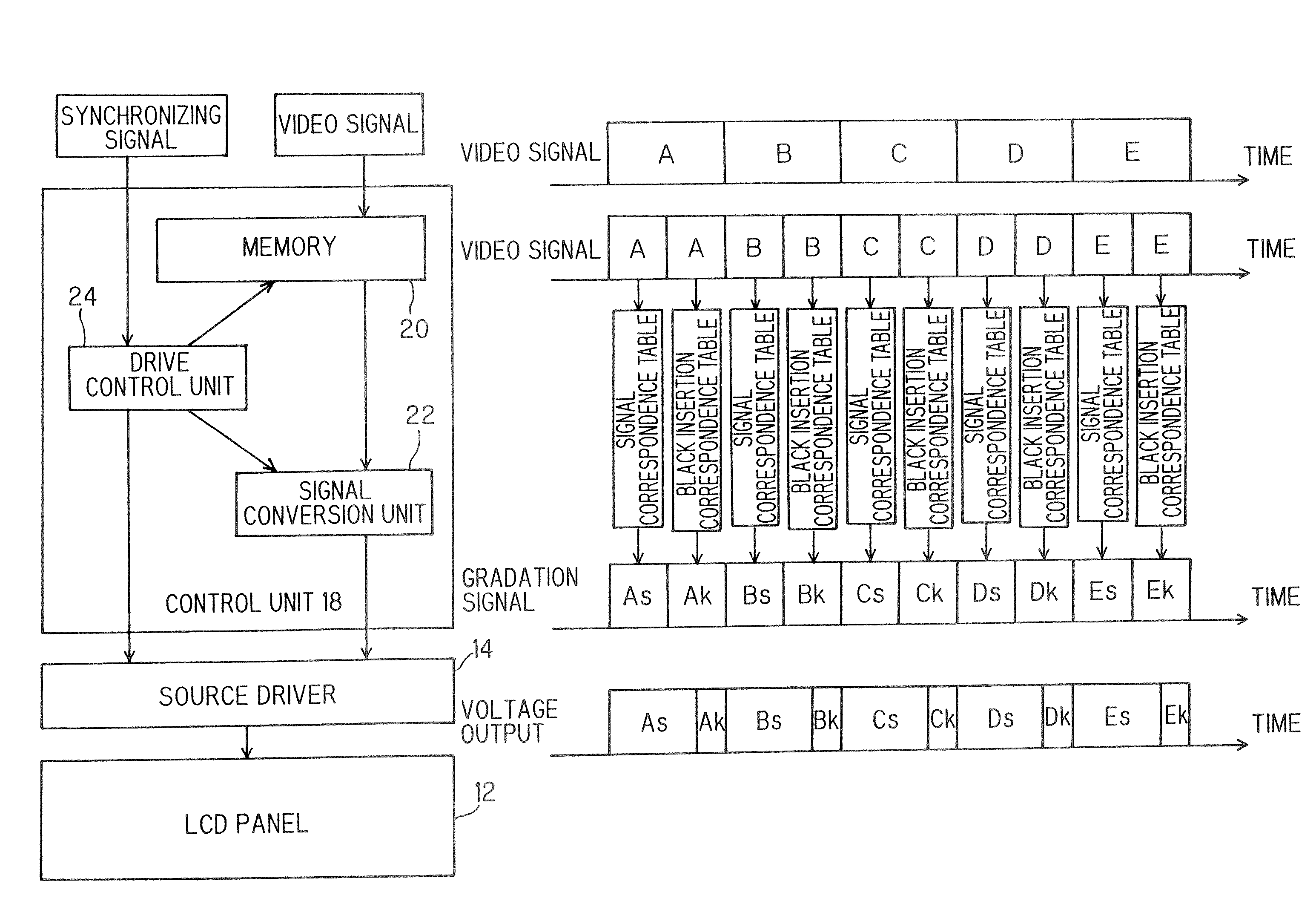
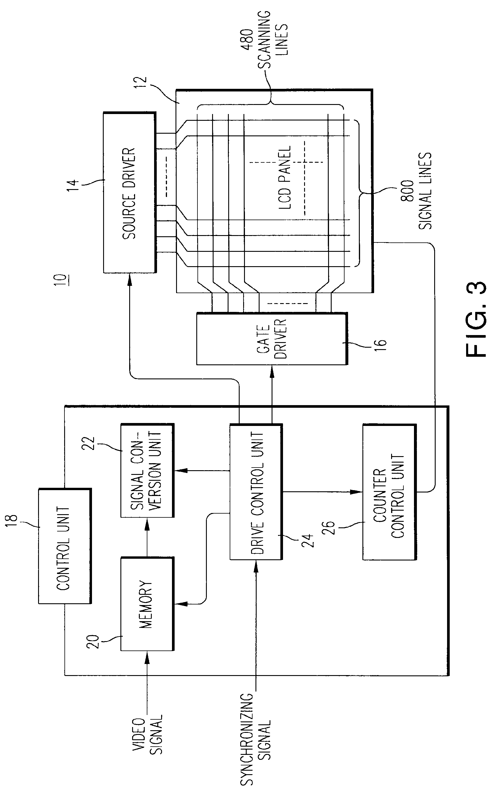
[0026]The structure of the liquid crystal display device 10 will be described based on the block diagram of FIG. 3.

[0027]A liquid crystal panel 12 of the liquid crystal display device 10 has an effective display area of 9 inches in diagonal size, and as described above, a liquid crystal is sandwiched between an array substrate and a counter substrate. On the array substrate, 800 signal lines and 480 scanning lines are disposed to be orthogonal to each other, and a polysilicon thin film transistor (TFT) is formed in the vicinity of each of intersections of the signal lines and the scanning lines. A source electrode of the TFT is connected to the signal line, a gate electrod...

second embodiment

[0044]An OCB liquid crystal display device 10 of a second embodiment will be described with reference to FIG. 9.

[0045]A different point between this embodiment and the first embodiment is that a memory 20 in which the foregoing correspondence table is stored and a signal conversion unit 22 are separate from a control unit 18, and a processing is performed as a set circuit 28 at the stage of a signal processing of an image receiving circuit. That is, in a recent video apparatus, especially in a digital display video apparatus, a frame memory is generally prepared, and display data for a signal and for a reverse transition prevention are created at the stage of a signal processing here. By this, redundancy of memories is avoided, and the signal processing is unified, so that the cost of the liquid crystal display device 10 can be reduced.

third embodiment

[0046]Next, a third embodiment will be described with reference to FIG. 10. FIG. 10 is a conceptual view of a correspondence table in the third embodiment.

[0047]In the first embodiment, the number of gradations of the reverse transition prevention voltage and that of the gradation voltage for the video display are 128 gradations and are equal to each other. However, in order to enrich the expression of the video display, the number of gradations of the video signal is increased, and the number of gradations of the reverse transition prevention voltage is reduced by that. For example, in the case where a 8-bit source driver 14 is used, when 128 gradations are allocated to the reverse transition prevention voltage, only the remaining 128 gradations are used for the video signal. However, a very larger number of gradations are not required for the reverse transition prevention voltage, and a suitable number of gradations (for example, 32 gradations) are sufficient for the reverse trans...


PUM


Abstract

In an OCB liquid crystal display device, a gradation voltage of a video signal is set to be lower than a black display optimum voltage, and a reverse transition prevention voltage is set to be higher than the black display optimum voltage and to be lower than a maximum applied voltage, and as the gradation voltage of the video signal becomes low, the reverse transition prevention voltage is set to be high.

Description

CROSS-REFERENCE TO RELATED APPLICATIONS[0001]This application is based upon and claims the benefit of priority from the prior Japanese Patent Application No. 2005-355104, filed on Dec. 8, 2005 and the prior Japanese Patent Application No. 2006-239546, filed on Sep. 4, 2006; the entire contents of which are incorporated herein by reference.TECHNICAL FIELD[0002]The present invention relates to a liquid crystal display device.BACKGROUND OF THE INVENTION[0003]Conventionally, a TN (Twisted Nematic) liquid crystal display device is generally used as a liquid crystal display device, however, in order to improve moving image visibility, an OCB liquid crystal display device characterized by high speed response is proposed.[0004]As shown in FIG. 1, in the OCB (Optically Compensated Bend) liquid crystal display device 100, an OCB liquid crystal 106 is sandwiched between an array substrate 102 and a counter substrate 104. In the array substrate 102, an array electrode 110 is formed on an upper ...

Claims


Application Information

Patent Timeline
Patent Type & Authority Patents(United States)
IPC IPC(8): G09G3/36
CPCG09G3/3648G09G2300/0491G09G2310/06G09G2310/061G09G2320/0238G09G2320/0261G09G2360/18
Inventor ARAKI, SHIGESUMINISHIYAMA, KAZUHIROOKITA, MITSUTAKASUZUKI, DAIICHI
Owner JAPAN DISPLAY CENTRAL CO LTD
Why Eureka
Try Eureka