Advanced signal processors for interference cancellation in baseband receivers

a signal processor and receiver technology, applied in the field of signal processing for wireless communications, can solve the problems of interference-limited cdma systems, and coded signals interfering with one another

Active Publication Date: 2010-08-31
III HLDG 1
View PDF151 Cites 116 Cited by
  • Summary
  • Abstract
  • Description
  • Claims
  • Application Information

AI Technical Summary

Problems solved by technology

However, multipath effects introduce cross correlations between codes and cause CDMA systems to be interference-limited.
While CDMA signaling has been useful in efficiently utilizing a given time-frequency band, multipath and other channel effects cause these coded signals to interfere with one another.
For example, coded signals may interfere due to similarities in codes and consequent correlation.
Loss of orthogonality between these signals results in interference, such as co-channel and cross-channel interference.
Co-channel interference may include multipath interference from the same transmitter, wherein a transmitted signal propagates along multiple paths that arrive at a receiver at different times. Cross-channel interference may include interference caused by signal paths originating from other transmitters.
Interference degrades communications by causing a receiver to incorrectly detect received transmissions, thus increasing a receiver's error floor.
Interference may also have other deleterious effects on communications.
For example, interference may diminish capacity of a communication system, decrease the region of coverage, and / or decrease data rates.
Multipath and other forms of interference inherently limit the performance and capacity of other types of transmission protocols.
For example, Orthogonal Frequency Division Multiplexing (OFDM) and Time Division Multiplexing (TDM) may be interference-limited both in uplink and downlink communications.

Method used


Image

  • Advanced signal processors for interference cancellation in baseband receivers
  • Advanced signal processors for interference cancellation in baseband receivers
  • Advanced signal processors for interference cancellation in baseband receivers

Examples


Embodiment Construction

[0026]While the invention is susceptible to various modifications and alternative forms, specific embodiments thereof are shown by way of example in the drawings and are herein described in detail. It should be understood, however, that the exemplary embodiments are not intended to limit the invention to the particular forms disclosed. Instead, the invention is to cover all modifications, equivalents, and alternatives falling within the spirit and scope of the invention as defined by the claims.

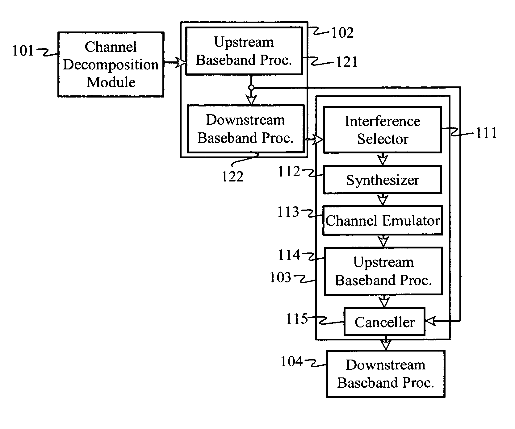
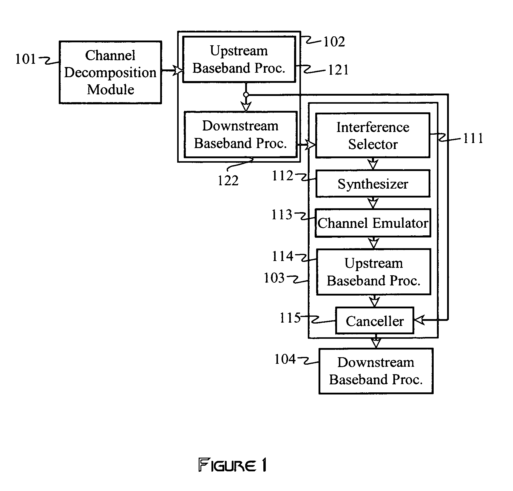
[0027]FIG. 1 illustrates one of many possible multi-mode receiver embodiments of the invention that include a channel decomposition module 101, a baseband receiver 102, and an interference canceller 103. The baseband receiver 102 and the interference canceller 103 are configured to process received signals transmitted in accordance with a first transmission protocol (i.e., a first mode).

[0028]The baseband receiver 102 may be regarded as comprising an upstream baseband processor 121 and a down...


PUM


Abstract

A multi-mode receiver includes a channel decomposition module (e.g., a Rake receiver) for separating a received signal into multipath components, an interference selector for selecting interfering paths and subchannels, a synthesizer for synthesizing interference signals from selected subchannel symbol estimates, and an interference canceller for cancelling selected interference in the received signal. At least one of the channel decomposition module, the synthesizer, and the interference canceller are configurable for processing multi-mode signals.

Description

CROSS-REFERENCE TO RELATED APPLICATIONS[0001]This application is a continuation-in-part of commonly owned U.S. patent application Ser. No. 11 / 100,935 (filed Apr. 7, 2005) now abandoned and U.S. patent application Ser. No. 11 / 192,763 (filed Jul. 29, 2005), now U.S. Pat. No. 7,463,609 which are incorporated by reference herein.BACKGROUND[0002]1. Field of the Invention[0003]The invention generally relates to the field of signal processing for wireless communications. More specifically the invention is related to interference cancellation in single- and multi-mode communication systems.[0004]2. Discussion of the Related Art[0005]In order to efficiently utilize time and frequency in a communication system, multiple-access schemes are used to specify how multiple users or multiple signals share a specified time and frequency allocation. Spread-spectrum techniques may be used to allow multiple users and / or signals to share the same frequency band and time interval simultaneously. Time divi...

Claims


Application Information

Patent Timeline
Patent Type & Authority Patents(United States)
IPC IPC(8): H04B1/10H04L1/00H04L25/08
CPCH04B1/7105H04B1/7107H04B1/7117H04B7/0678H04B7/0891H04J13/20H04B1/712H04B1/126H04J13/0022H04B1/1027H04B1/1081H04B2001/1045H04B2201/70719H04B2201/70979
Inventor SCHARF, LOUIS L.NAGARAJAN, VIJAY
Owner III HLDG 1
Why Eureka
Try Eureka