Supercharge Your Innovation With Domain-Expert AI Agents!

Perforating gun loading bay, table and method

a perforating gun and loading bay technology, applied in the direction of weapons, ammunition, armoured vehicles, etc., can solve the problems of complex perforating gun loading operations, insufficient attention of loading facilities to the risk of injury to personnel and equipment, and often an issue of security, so as to mitigate some of the risks in loading and handling.

Inactive Publication Date: 2010-09-07
1323079 ALBERTA LTD
View PDF27 Cites 1 Cited by
  • Summary
  • Abstract
  • Description
  • Claims
  • Application Information

AI Technical Summary

Benefits of technology

"The patent describes a perforating gun loading table and a perforating gun loading bay that can mitigate risks associated with loading and handling explosive charges used in perforating guns. The invention includes a blast mitigation wall and a worker walk way through the blast mitigation wall. The invention also includes a method for loading a perforating gun by placing a perforating gun strip onto rollers, loading explosives, and sliding the outer housing of the gun over the strip with the explosives positioned within. The technical effects of the invention include reducing risks associated with loading and handling perforating guns, improving safety during the loading process, and increasing efficiency in the loading process."

Problems solved by technology

Security is often an issue since these areas are often open to the remainder of the shop.
However, recently, it has become apparent that present loading facilities sometimes do not adequately address the risk of injury to personnel and equipment should an accidental detonation occur.
In particular, the shrapnel generated by an accidental detonation perforating gun detonation can pass into adjacent open or separated work areas injuring personnel who are not at all involved in the handling of explosives or in the industry of perforating guns in general.
As will be appreciated, this has complicated perforating gun loading operations as it is often very difficult to provide safe quantity distance about the entire bay.
Another problem that must be addressed is relating to storage of the explosives.
This often requires that the explosive be transported into and out of magazines on a regular basis, which increases the chances of accidents.

Method used


Image

  • Perforating gun loading bay, table and method
  • Perforating gun loading bay, table and method
  • Perforating gun loading bay, table and method

Examples


Embodiment Construction

[0022]The detailed description set forth below in connection with the appended drawings is intended as a description of various embodiments of the present invention and is not intended to represent the only embodiments contemplated by the inventor. The detailed description includes specific details for the purpose of providing a comprehensive understanding of the present invention. However, it will be apparent to those skilled in the art that the present invention may be practiced without these specific details.

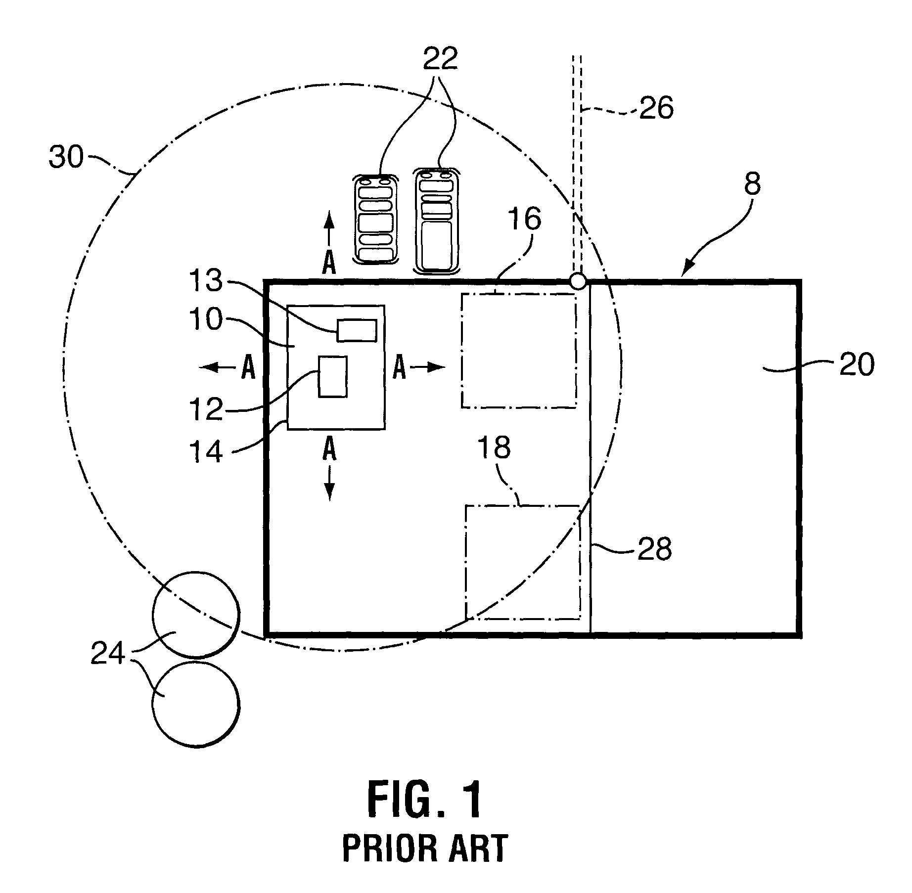
[0023]FIG. 1 shows a schematic layout of a typical prior art perforating gun loading shop 8 including a loading area 10 including a bench 12 on which the gun is loaded and a magazine 13 in which the explosives for the gun are stored. The loading area, as is common practice, is identified in the shop by a red line 14 which indicates a risk area into which entry is permitted only by authorized personnel. Generally, the area will contain less than 20 kg of explosives including t...


PUM


Abstract

A perforating gun loading bay includes a loading area and a separate gun component storage area. The perforating gun loading area also includes racks and a table that permit an in-line loading operation such that the gun housing and loaded gun need not be moved out of a linear path from introduction to the bay to unloading from the bay. The racks and the table may be position in axial alignment and may include low friction members to permit axial sliding motion along the racks and the table. A method for using the loading bay permits in-line handling. A perforating gun loading table includes low friction members permitting axial movement of perforating gun components therealong and low friction members permitting rotational movement of perforating gun components along their long axis. The perforating gun loading table includes a control system for selecting the low friction member that is positioned to engage the perforating gun component on the table.

Description

FIELD OF THE INVENTION[0001]The present invention relates to a perforating wireline gun loading and, in particular, a bay in which and a method for which the explosives for perforating guns can be handled and loaded while mitigating the risk of damage due to accidental detonation.BACKGROUND[0002]Explosives are used widely throughout the world for a variety of applications including oilfield and mining. One application of explosives used commonly in the oil industry is the use of perforating guns, which are also termed wireline guns. The perforating guns are tubular assemblies that contain a series of explosive shaped charges. When detonated the shaped charges create a molten high-pressure jet that creates a perforation into the hydrocarbon bearing formation. The hydrocarbons can then flow into the wellbore for production of the well.[0003]These perforating guns are commonly loaded (with shaped explosive charges) in shops or specially designated areas for safety concerns. These requi...

Claims


Application Information

Patent Timeline
Patent Type & Authority Patents(United States)
IPC IPC(8): F42B33/00
CPCF42D3/04F42B33/001F42B33/00
Inventor WALKER, TROY S.
Owner 1323079 ALBERTA LTD
Features
  • R&D
  • Intellectual Property
  • Life Sciences
  • Materials
  • Tech Scout
  • Unparalleled Data Quality
  • Higher Quality Content
  • 60% Fewer Hallucinations
Learn More