Using a fixed-frequency oscillation to detect and measure scene inhomogeneity

Active Publication Date: 2010-09-07
HARRIS CORP
View PDF10 Cites 0 Cited by
  • Summary
  • Abstract
  • Description
  • Claims
  • Application Information

AI Technical Summary

Benefits of technology

[0007]Yet another embodiment of the invention is an optical system for measuring scene inhomogeneity. The system includes a dichroic mirror for receiving radiance of a field-of-view (FOV) of a scene, and reflecting a portion of the radiance to an optical detector. A controller is coupled to the mirror for changing the FOV. The optical detector provides a signal of the reflected portion of radiance of the scene. A processor determines scene inhomogeneity, based on amplitude of the signal provided from the optical detector. The controller is configured to change the FOV at a periodic interval, using one of a sinusoidal waveform, a pulse code modulated waveform, or a pseudo-random waveform. The processor is configured to determine scene inhomogeneity, based on the signal provided from the optical detector having a waveform corresponding to the respective sinusoidal waveform, the pulse code modulated waveform, or the pseudo-random waveform. The optical detector includes a focal planar array (FPA) for detecting the radiance of the scene and providing multiple output signals from the FPA, and the processor includes an adder for summing the multiple output signals from the FPA. The processor is configured to determine that the secne is inhomogeneous, when the amplitude of the signal is larger than a noise component of the signal. The processor is configured to determine that the scene is homogeneous, when the measured amplitude of the signal is eq

Problems solved by technology

If the scene radiance does in fact vary—for example, because the line-of-sight (LOS) of the instrument changes for an inhomogeneous scene—then the radiance may not be analyzed accurately.
If the LOS change is random, this can become a significant source of analysis error.
When sounding planetary atmospheres, scene inhomogeneity due to the presence of clouds is a significant source of noise or uncertainty.
None of these methods, however, can unambiguously determine the degree of scene inhomogeneity for an individual field-of-view (FOV) because they require the observation of multiple or adjacent fields of view.

Method used


Image

  • Using a fixed-frequency oscillation to detect and measure scene inhomogeneity
  • Using a fixed-frequency oscillation to detect and measure scene inhomogeneity
  • Using a fixed-frequency oscillation to detect and measure scene inhomogeneity

Examples


Embodiment Construction

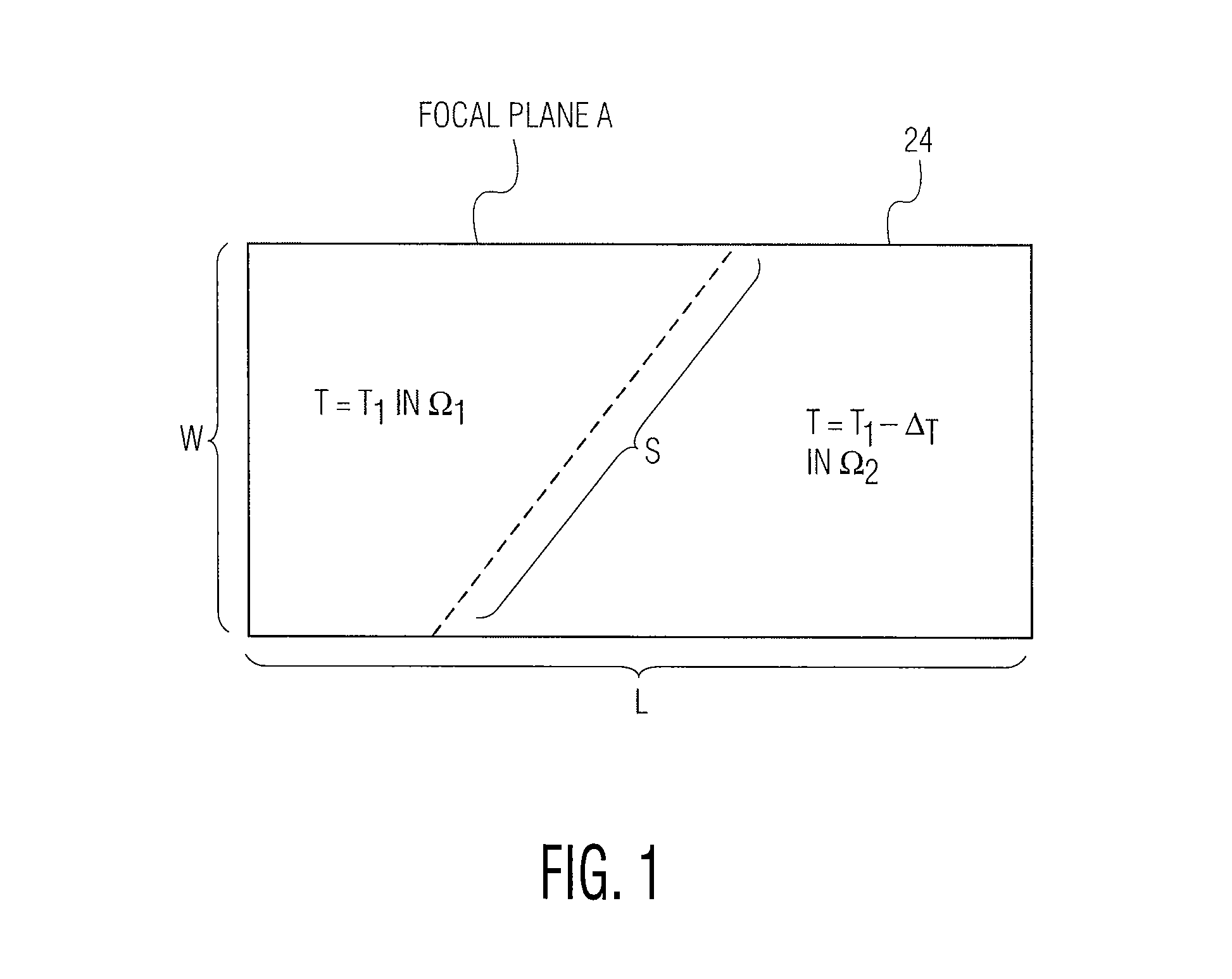
[0015]If a small, uniform oscillation is placed on an optical instrument's line-of-sight (LOS), and the instrument is observing a scene which is inhomogeneous at the edges of the field-of-view (FOV), then the output may include an oscillating signal whose amplitude is proportional to the degree of scene inhomogeneity present in the scene. When this oscillation is small or undetectable, then the scene is only slightly inhomogeneous. It is probably cloud-free or covered by the same type of cloud layer. If the opposite is true, then the scene is significantly inhomogeneous, probably having a relatively large fraction of the FOV filled with different types of cloud or other sources of distinct radiances.

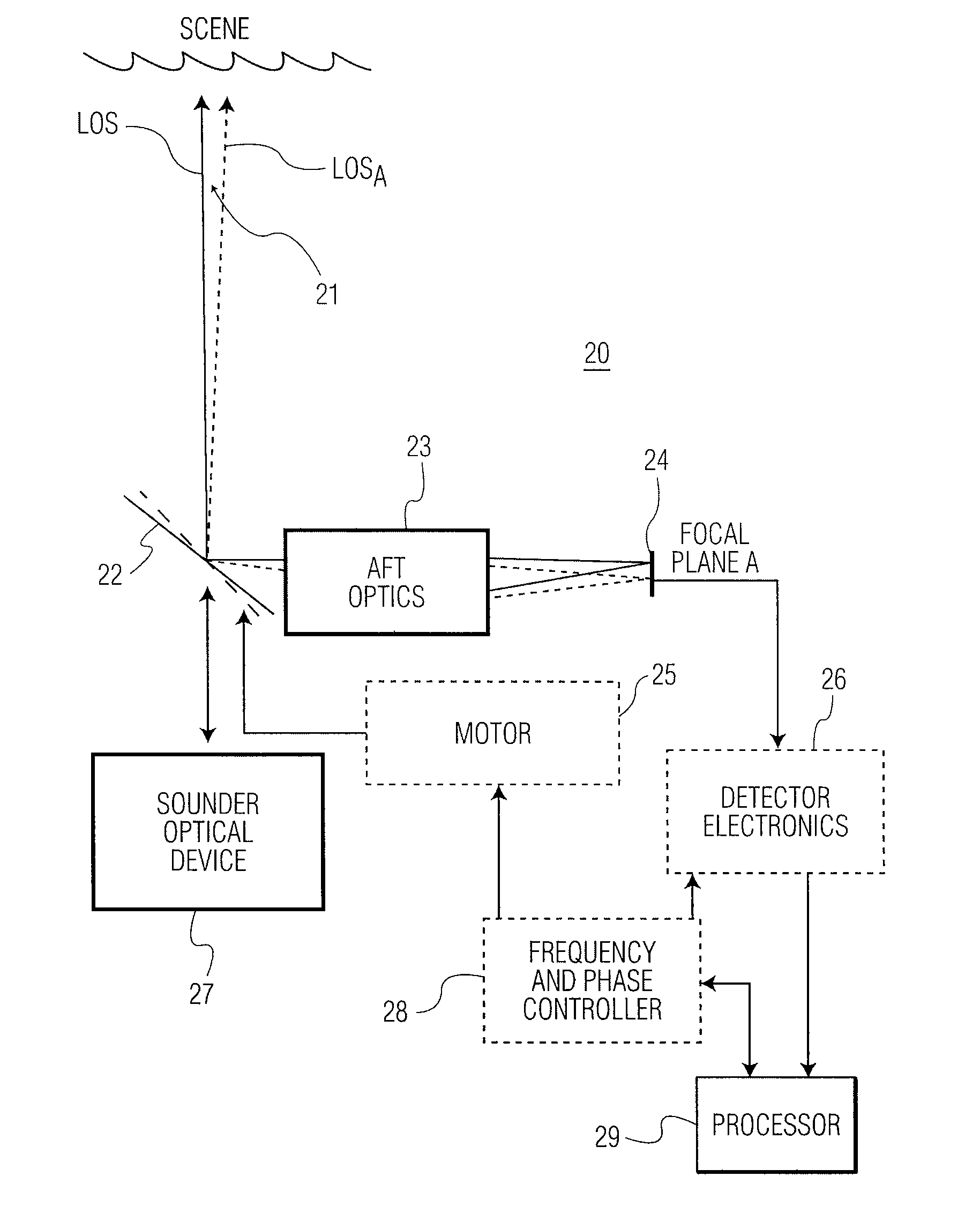
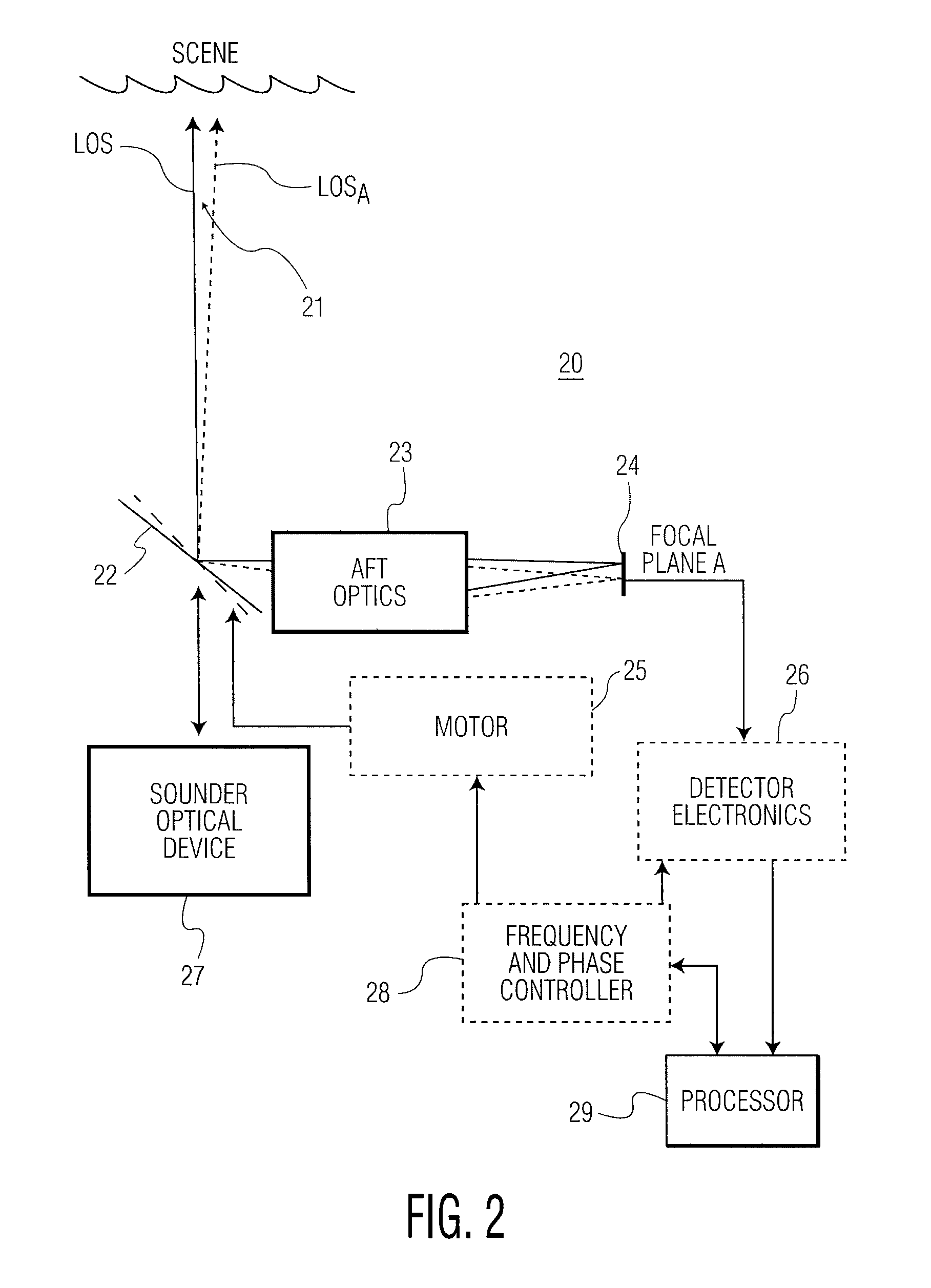
[0016]Referring to FIG. 2, sounder optical device 27 receives scene radiance, shown as an optical beam transmitted through mirror 22. The optical beam is transmitted, as shown, by way of a line-of-sight (LOS) to the scene. Mirror 22 is configured to transmit (pass through) any long wavel...


PUM


Abstract

An optical system measures scene inhomogeneity. The system includes a mirror for receiving radiance of a field-of-view (FOV) of a scene, and reflecting a portion of the radiance to an optical detector. A controller is coupled to the mirror for changing the FOV. The optical detector provides a signal of the reflected portion of radiance of the scene. A processor determines scene inhomogeneity, based on amplitude of the signal provided from the optical detector. The controller is configured to modulate the FOV at a periodic interval, using a sinusoidal waveform, a pulse code modulated waveform, or a pseudo-random waveform.

Description

CROSS REFERENCE TO RELATED APPLICATIONS[0001]This application claims priority of U.S. Provisional Patent Application No. 60 / 880,268 filed Jan. 12, 2007, and is incorporated herein by reference in its entirety.[0002]The present invention is related to U.S. application Ser. No. 11 / 159,883 filed on Jun. 23, 2005, by the same inventive entity, and is incorporated herein by reference in its entirety.TECHNICAL FIELD[0003]The present invention relates, in general, to a method and apparatus for observation of atmospheric spectra or scene spectral radiance. More specifically, the present invention relates to a method and apparatus for measuring scene inhomogeneity, by adding a repetitive pattern of line-of-sight (LOS) oscillation to a field-of-view (FOV) of an optical instrument.BACKGROUND OF THE INVENTION[0004]Conventional optical packages assume that the scene radiance does not vary while it is being analyzed. If the scene radiance does in fact vary—for example, because the line-of-sight (...

Claims


Application Information

Patent Timeline
IPC IPC(8): G01J1/56G01P3/40
CPCG01J1/02G01J1/0266G01J1/04G01J1/0403G01J1/08G01J5/007G01J5/04G01J5/047G01J5/08G01J5/089G01J2005/0048G01J5/80G01J5/07
Inventor COHEN, DOUGLAS LENTCRAIN, DAVID JAMESHERTEL, RICHARD JAMES
Owner HARRIS CORP
Why Eureka
Try Eureka