Detection of an electromagnetic signal

a detection method and electromagnetic signal technology, applied in the direction of electromagnetic transmission, direction finders using electromagnetic waves, transmission, etc., to achieve the effect of extending the operational range of the signal detector, enhancing the performance of the signal detector having a low on-time, and increasing the chance of detecting an even

Inactive Publication Date: 2010-09-07
MBDA UK
View PDF17 Cites 70 Cited by
  • Summary
  • Abstract
  • Description
  • Claims
  • Application Information

AI Technical Summary

Benefits of technology

[0008]According to one aspect of the present invention a signal detection system comprises an electromagnetic signal detector having a limited on-time for detecting receipt of electromagnetic signals, at least two optical paths arranged to receive an electromagnetic signal from the same nominal direction in space and to transmit any received signal towards the signal detector, an optical time delay operative within one of the optical paths to delay transmission of any received signal towards the signal detector, and the optical time delay is selected to extend the operational range of the signal detector by compressing the real time during which a signal can be received into the shorter on-time of the signal detector. In this manner the performance of a signal detector having a low on-time is substantially enhanced, by extending the effective duty cycle over which data can be collected. For a passive system the chances of detecting an event are increased by the extended duty cycle. For an active system the search volume is increased and the chances of detecting an object are also increased.

Problems solved by technology

However, any convenient form of optical time delay may be positioned within an optical path subject, of course, to the operational parameters of the electromagnetic signal processing system.

Method used


Image

  • Detection of an electromagnetic signal
  • Detection of an electromagnetic signal
  • Detection of an electromagnetic signal

Examples


Embodiment Construction

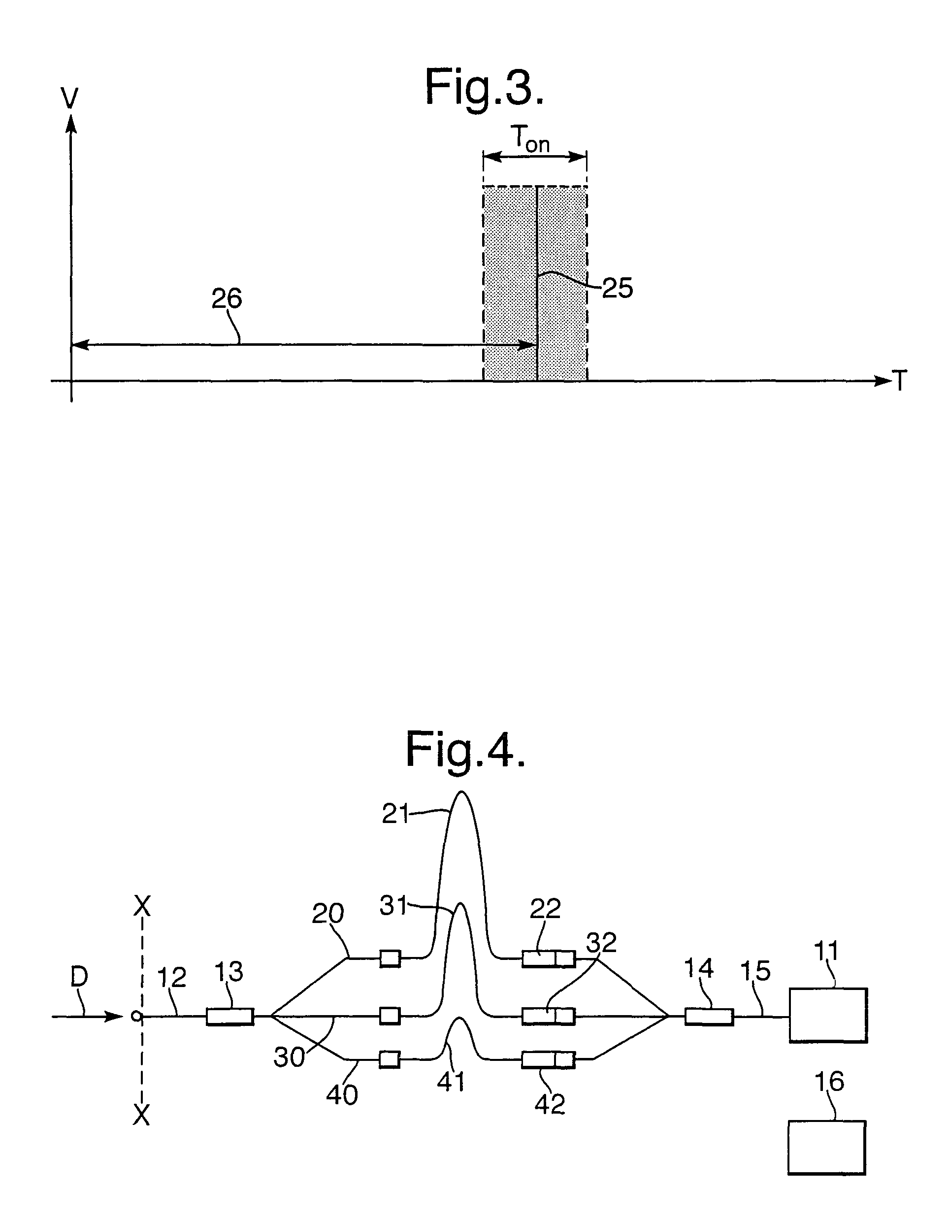
[0028]Signal detectors of various designs are well known in the art and have a short duty cycle. This duty cycle is commonly known as the ‘on-time’.

[0029]Minimising the on-time of a signal detector reduces detector noise, that is a background signal from the atmosphere and the clutter around an object to be detected, and increases the maximum range capability of the entire signal detection system. However, with any signal detection system, it is essential for the detector on-time to coincide with the arrival time of the signal.

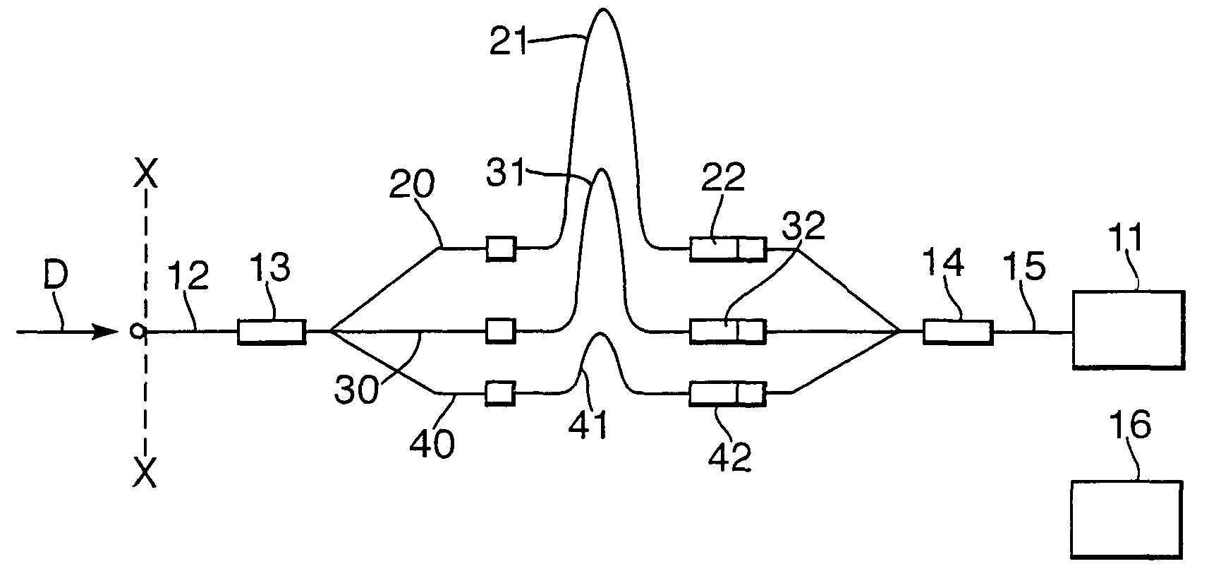
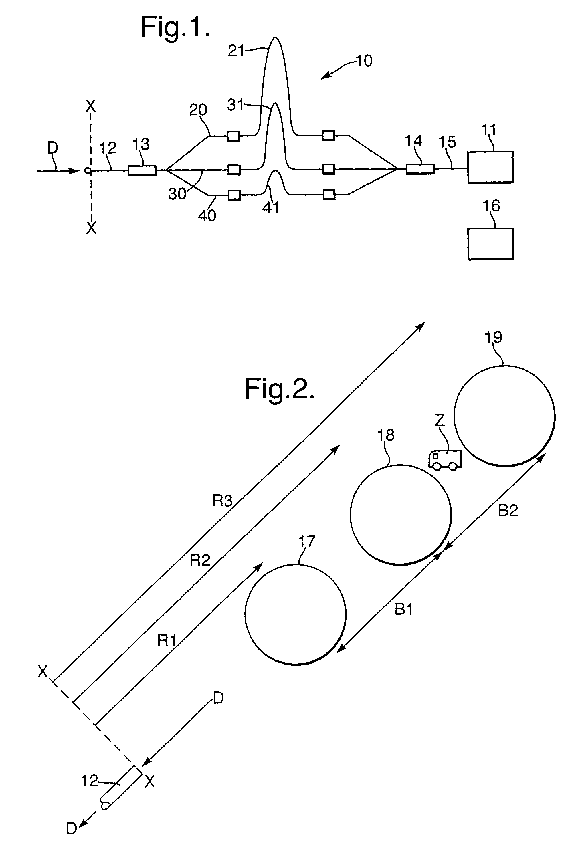
[0030]With reference to FIG. 1 a signal detection system 10 comprises a single signal detector 11 having a limited on-time during which any received electromagnetic signal can be assessed, that is detected and processed. The signal detector 11 receives electromagnetic signals from a single direction in space D through a single optical fibre 12, a signal splitter 13 which splits the collected signal between three optical paths 20, 30, and 40, and a signal combi...


PUM


Abstract

A signal detector system (10) comprises a single signal detector (11) having a limited on-time during which any received electromagnetic signal can be assessed. The signal detector (11) receives electromagnetic signals from a single direction in space (D) through a single optical fibre (12), a signal splitter 13 which splits the collected signal between three optical paths (20, 30 and 40), and a signal combiner (14) which combines the portions of the signal transmitted by the three optical paths (20, 30 and 40) and transmits the combined signal to a signal detector input (15). Each of the optical paths (20, 30 and 40) includes a respective optical delay (21, 31 and 41) designed to delay transmission of any received signal towards the signal detector (11). In this manner the signal detector (11) will receive any signals that arrived at the optical fibre (12) during three separate periods of time.

Description

[0001]This application is the US national phase of international application PCT / GB2004 / 004616, filed in English on 1 Nov. 2004, which designated the US. PCT / GB2004 / 004616 claims priority to GB Application No. 0325785.4 filed 5 Nov. 2003. The entire contents of these applications are incorporated herein by reference.BACKGROUND OF THE INVENTION[0002]1. Field of the Invention[0003]This invention relates to both a system and a method of detecting an electromagnetic signal.[0004]2. Discussion of Prior Art[0005]It is well known for electromagnetic energy emanating from an object to be detected as a signal by a passive detection system. It is also well known for an active detection system to detect an electromagnetic signal reflected by an object illuminated by an electromagnetic energy transmitter.[0006]The detection of an electromagnetic signal by both passive and active systems involves the use of a signal detector which may have a very short ‘on-time’, that is the time during which th...

Claims


Application Information

Patent Timeline
Patent Type & Authority Patents(United States)
IPC IPC(8): H04B10/00G01S3/783G01S7/48G01S7/481
CPCG01S3/783G01S7/4804G01S7/4818
Inventor JENNINGS, MARTYN RRICHARDS, THOMAS J
Owner MBDA UK
Why Eureka
Try Eureka