Multi-band frequency synthesizer

a synthesizer and multi-band technology, applied in the direction of pulse generators, pulse manipulation, digital transmission, etc., can solve the problems of double-loop architecture, double-loop architecture requires effectively twice the chip area, and a challenging design problem, so as to improve phase noise performance

Inactive Publication Date: 2010-09-07
SONY ERICSSON MOBILE COMM AB
View PDF15 Cites 9 Cited by
  • Summary
  • Abstract
  • Description
  • Claims
  • Application Information

AI Technical Summary

Benefits of technology

[0067]The exemplary frequency plan of FIG. 3 further shows the filter characteristic of the low-pass filter 214 (LPF1) indicating that its bandwidth is sufficiently broad to allow a fast switching of frequencies at the VCO 215, but also sufficiently narrow to prevent phase noise in the output spectra of the first PLL frequency synthesizer 211.

Problems solved by technology

This poses a challenging design problem.
There are many challenges faced in designing a multi-band CMOS frequency synthesizer.
However, this double-loop architecture requires effectively twice the chip area as a standard single-loop PLL circuitry.
Integrated voltage-controlled oscillators used in PLL-based frequency synthesizers generally have limited tuning ranges or conversion gains.
However, this oscillator suffers from a very limited tuning range because it is tuned with varactor capacitors that generally make up only 25% of the total capacitance.
However, as such a large conversion gain is not available with conventional integrated VCOs, their output spectra are severely distorted by phase noise.
The main drawback of all classes of fractional-N frequency synthesizers is their bad output spectrum performance which is characterized by high phase noise and a high amount of spurious harmonics.
Especially when receiving low-level signals, this can be very problematic.
When using fractional-N frequency synthesizers, the requirements of the GSM standard 0505 can only be achieved by postprocessing the output spectra with high-quality filters, which are bulky and cost-intensive.
The disclosed transceiver architecture can not be applied to multi-mode operation, however, because it does not comprise any multi-band frequency synthesizing unit.

Method used


Image

  • Multi-band frequency synthesizer
  • Multi-band frequency synthesizer
  • Multi-band frequency synthesizer

Examples


Embodiment Construction

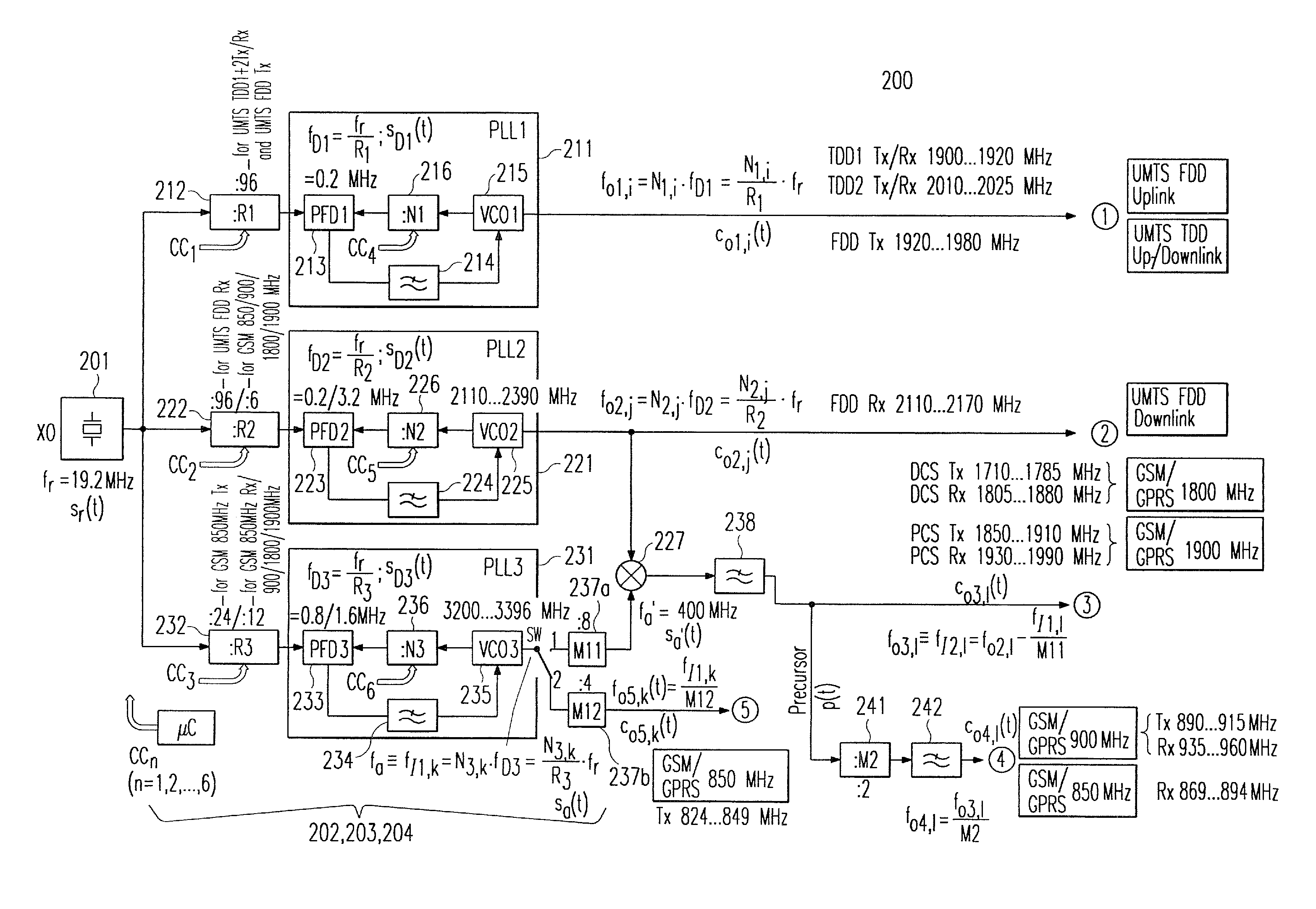
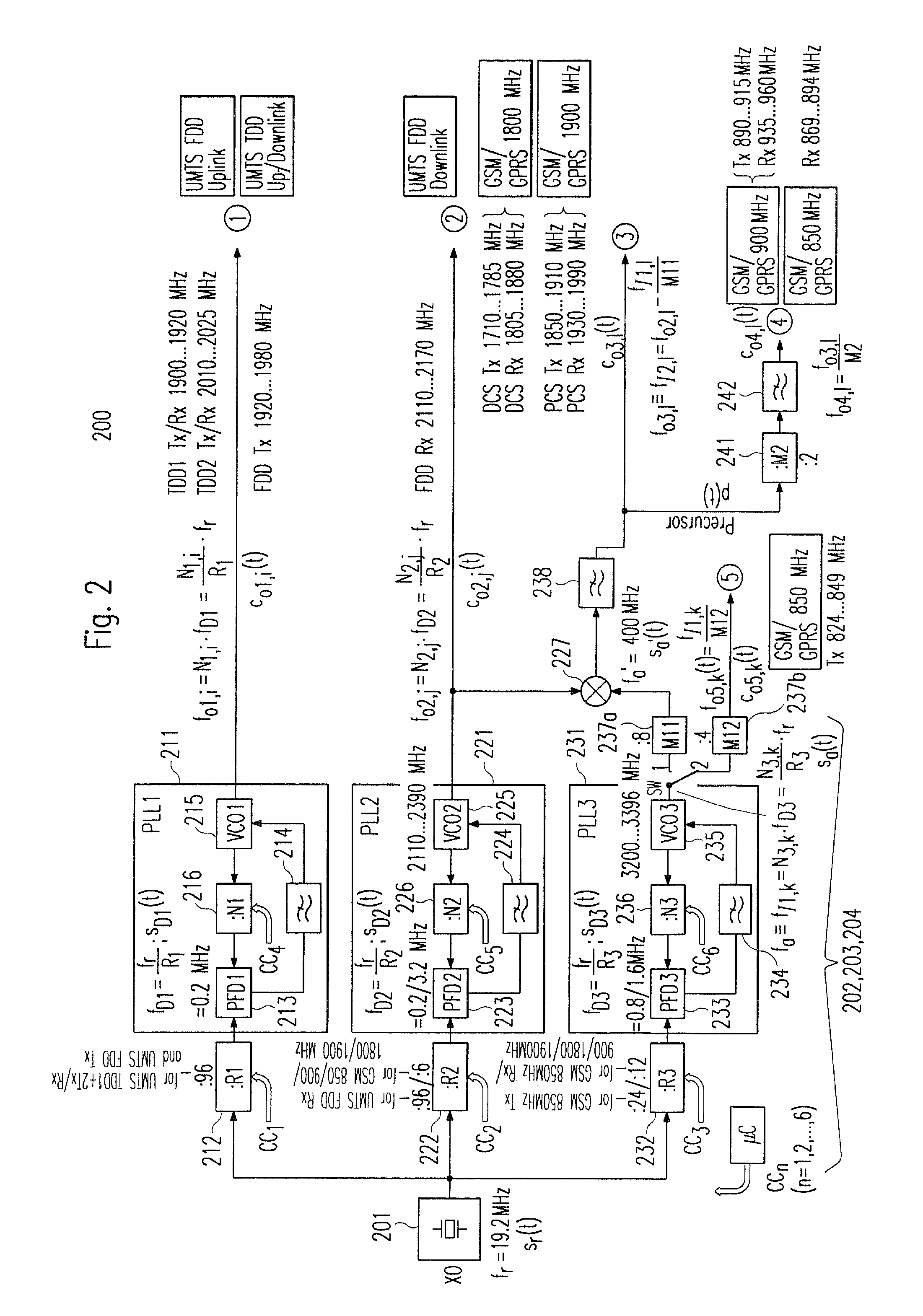
[0028]In the following, one embodiment of the underlying invention as depicted in FIG. 2 shall be explained in detail.

[0029]The embodiment implements a method for operating a multi-band frequency synthesizer 200 of a wireless multi-mode transceiver for generating tunable carrier signals c01,i(t), co2,j(t), co3,l(t), and co4,l(t) whose frequencies fo1,i, fo2,j, fo3,l, and fo4,l are located in different frequency bands and assigned to the up- and downlink channels of a number of wireless communication standards (f.e. GSM / GPRS 900 MHz Tx / Rx, GSM / GPRS (DCS) 1,800 MD Tx / Rx, GSM / GPRS (PCS) 1,900 MHz Tx / Rx, UMTS TDD1 Tx / Rx, UMTS TDD2 Tx / Rx, and UMTS FDD Tx / Rx), respectively. The method comprises the steps of providing (S1) an oscillator signal sr(t) with a constant reference frequency fr of 19.2 MHz, converting (S2) said oscillator signal sr(t) into a first carrier signal co1,i(t) having a frequency fo1,i in the range of a first frequency band (UMTS TDD1+2 Tx / Rx, UMTS FDD Tx), and converti...


PUM


Abstract

A multi-mode PLL frequency synthesizer of a wireless multi-mode transceiver is provided which includes a reference frequency source providing an oscillator signal with a constant reference frequency, a first frequency synthesizer subunit for converting the signal into carrier signals with frequencies in the range of a first frequency band, a second frequency synthesizer subunit for transforming the oscillator signal into carrier signals having frequencies in the range of a second frequency band, and a third frequency synthesizer subunit for converting the oscillator signal into an auxiliary signal with a fixed frequency. The auxiliary signal is used together with the carrier signals of the second frequency band to generate carrier signals with frequencies in the range of a third and fourth frequency band. A frequency divider derives a signal in the range of a fifth frequency band from further intermediate frequency signals supplied by the third frequency synthesizer subunit by dividing the frequency of the auxiliary signal by an integer value.

Description

RELATED APPLICATIONS[0001]The present application is a 35 U.S.C. §371 national phase application of PCT International Application No. PCT / EP2004 / 000046, having an international filing date of Jan. 7, 2004, and claiming priority to European Patent Application No. 03005322.7, filed Mar. 11, 2003, the disclosures of which are incorporated herein by reference in their entireties. The above PCT International Application was published in the English language and has International Publication No. WO 2004 / 082160 A1.FIELD OF THE INVENTION[0002]The present invention generally relates to the field of multi-band frequency synthesizer architectures, which can advantageously be applied to wireless multi-mode transceivers in a cellular telecommunication system based on f.e. UMTS or GSM / GPRS technology. It particularly refers to a multi-band frequency synthesizer comprising three frequency synthesizer subunits for generating carrier signals with carrier frequencies suitable f.e. for UMTS and GSM / GP...

Claims


Application Information

Patent Timeline
Patent Type & Authority Patents(United States)
IPC IPC(8): H04B7/00H04B1/40
CPCH04B1/005H04B1/406
Inventor PESTRYAKOV, ALEXANDERSMIRNOV, ALEXEJ
Owner SONY ERICSSON MOBILE COMM AB
Why Eureka
Try Eureka