A Sweeping Frequency Source Based on Single Sideband Modulation and Cyclic Frequency Shifting

A single-sideband modulation and sweeping source technology, applied in the field of sweeping sources, can solve the problems of sweeping adjustment speed, stability and accuracy limitations, small frequency shift range, difficulty in achieving fast frequency switching and stable power, etc. , to achieve the effects of high stability and precision, fast frequency switching speed, and large frequency shift range

Active Publication Date: 2016-03-30
TSINGHUA UNIV
View PDF3 Cites 0 Cited by
  • Summary
  • Abstract
  • Description
  • Claims
  • Application Information

AI Technical Summary

Problems solved by technology

[0005] First, it usually takes a certain amount of time for the laser to establish a stable oscillation at a specific wavelength. By adjusting the resonance conditions of the laser to change the wavelength of the output optical signal, it will be limited by the establishment of the oscillation time of the laser, so it is difficult to achieve fast frequency switching and stabilization. power of optical signal output;
[0006] Second, the resonance conditions of the laser are adjusted mechanically, so the speed, stability and accuracy of frequency sweep adjustment are limited;
[0007] Third, the frequency shift range is small, limited by the tuning range of the laser's operating wavelength, usually only covering one band, such as C-band or L-band

Method used


Image

  • A Sweeping Frequency Source Based on Single Sideband Modulation and Cyclic Frequency Shifting
  • A Sweeping Frequency Source Based on Single Sideband Modulation and Cyclic Frequency Shifting
  • A Sweeping Frequency Source Based on Single Sideband Modulation and Cyclic Frequency Shifting

Examples


Embodiment 1

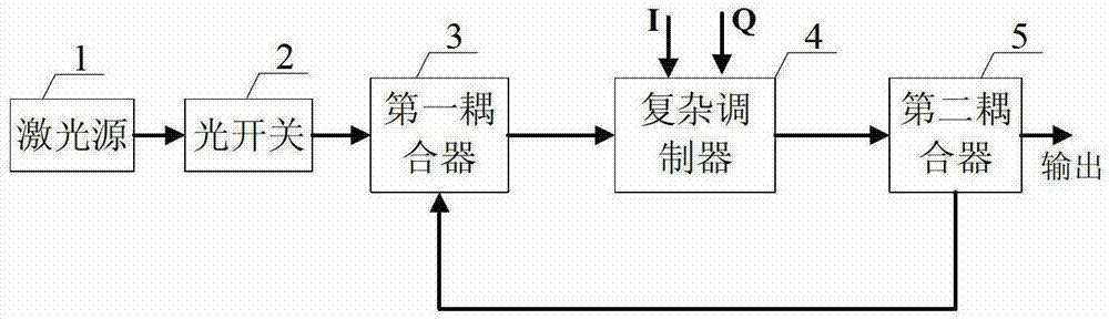
[0030] The frequency sweeping source based on single sideband modulation and cyclic frequency shift provided in this embodiment includes a laser source 1, an optical switch 2, a first coupler 3, a complex modulator 4 and a second coupler 5, such as figure 1 shown. The laser source 1 is sequentially connected to the optical switch 2, the first coupler 3, the complex modulator 4 and the second coupler 5 through optical fibers. The second coupler 5 has two output terminals. The first output end of the second coupler 5 is connected to the first coupler 3 through an optical fiber, so that the first coupler 3 , the complex modulator 4 and the second coupler 5 form a loop. The second output terminal of the second coupler 5 is used as the output terminal of the frequency sweep source to connect with external devices. In this embodiment, the complex modulator 4 includes two Mach-Zehnder modulators (not shown in the figure).

[0031] The laser source 1 is used to generate a continuou...

Embodiment 2

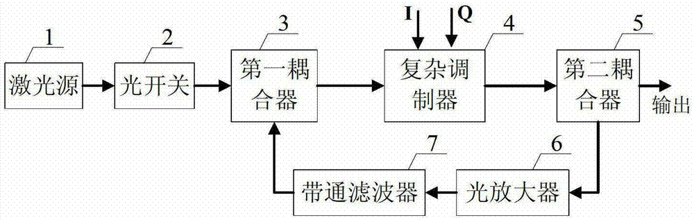
[0036] The frequency-sweeping source based on single-sideband modulation and cyclic frequency shift provided in this embodiment includes a laser source 1, an optical switch 2, a first coupler 3, a complex modulator 4, a second coupler 5, an optical amplifier 6 and a band-pass filter 7, such as figure 2 shown. The laser source 1 is sequentially connected to the optical switch 2, the first coupler 3, the complex modulator 4 and the second coupler 5 through optical fibers. The second coupler 5 has two output terminals. The first output end of the second coupler 5 is sequentially connected with the optical amplifier 6, the bandpass filter 7 and the first coupler 3 through an optical fiber, so that the first coupler 3, the complex modulator 4, the second coupler 5, the optical Amplifier 6 and bandpass filter 7 form a loop. The second output terminal of the second coupler 5 is used as the output terminal of the frequency sweep source to connect with external devices. In this em...

Embodiment 3

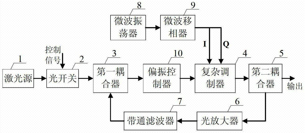
[0042] The frequency-sweeping source based on SSB modulation and cyclic frequency shift provided in this embodiment includes a laser source 1, an optical switch 2, a first coupler 3, a complex modulator 4, a second coupler 5, an optical amplifier 6, a band-pass Filter 7, microwave oscillator 8, microwave phase shifter 9 and polarization controller 10, such as image 3shown. A laser source 1 is sequentially connected to an optical switch 2 , a first coupler 3 , a polarization controller 10 , a complex modulator 4 and a second coupler 5 through optical fibers. The second coupler 5 has two output terminals. The first output end of the second coupler 5 is sequentially connected with the optical amplifier 6, the bandpass filter 7 and the first coupler 3 through an optical fiber, so that the first coupler 3, the polarization controller 10, the complex modulator 4, the second Coupler 5, optical amplifier 6 and bandpass filter 7 form a loop. The second output terminal of the second...


PUM


Abstract

The invention provides a frequency-sweeping source based on single-sideband modulation and circulating frequency shifting. The frequency-sweeping source comprises a laser source (1), a photo switch (2), a first coupler (3), a complex modulator (4) and a second modulator (5), wherein the laser source (1) is used for producing continuous photosignals, the photo switch (2) is used for converting the continuous photosignals from the laser source (1) into periodical pulse photosignals, the first coupler (3) is used for merging photosignals from the photo switch (2) and the second modulator (5) into a path, the complex modulator (4) is driven by two paths of microwave signals with the same frequency and amplitude and a phase difference of pi / 2 to enable frequency of the photosignals from the first coupler (3) to be shifted, the direction of frequency shifting is decided by a bias state of the complex modulator (4), and the second modulator (5) is used for separating the photosignals from the complex modulator (4) into two paths of photosignals, wherein one path of photosignals are input into the first coupler (3), the other path of photosignals are output for use. The frequency-sweeping source is fast in frequency switching speed, stable in output power, high in speed, stability and precision of frequency-sweeping regulation, and large in frequency-shifting range.

Description

technical field [0001] The invention relates to the field of optoelectronic technology, in particular to a frequency sweeping source based on single sideband modulation and cyclic frequency shifting. Background technique [0002] With the rapid development of optoelectronic technology, the advantages of fast transmission speed and large bandwidth of optical signals are gradually favored by technicians and users. In high-speed signal acquisition systems and optical scanning imaging systems, frequency-sweeping sources in which the wavelength of the output optical signal changes uniformly with time are often required. [0003] In the prior art, the frequency-sweeping source mainly controls the wavelength of the output optical signal by adjusting the resonance condition of the laser, for example, by adjusting the length of the resonant cavity of the laser or adding an adjustable filter in the resonant cavity to control the output. The wavelength of the optical signal. [0004]...

Claims


Application Information

Patent Timeline
Patent Type & Authority Patents(China)
IPC IPC(8): H04B10/572
Inventor 陈宏伟雷诚陈明华杨四刚谢世钟
Owner TSINGHUA UNIV
Why Eureka
Try Eureka