
Operating devices and methods for electronic percussion instrument

a technology of operating devices and electronic percussion instruments, which is applied in the direction of instruments, instruments, instruments, etc., can solve the problems that the electronic percussion instrument b>200/b> is not adapted to be fastened, and achieve the effect of improving the operability of the operators and easy reach

Inactive Publication Date: 2010-09-14
ROLAND CORP
View PDF13 Cites 12 Cited by
  • Summary
  • Abstract
  • Description
  • Claims
  • Application Information

AI Technical Summary

Benefits of technology

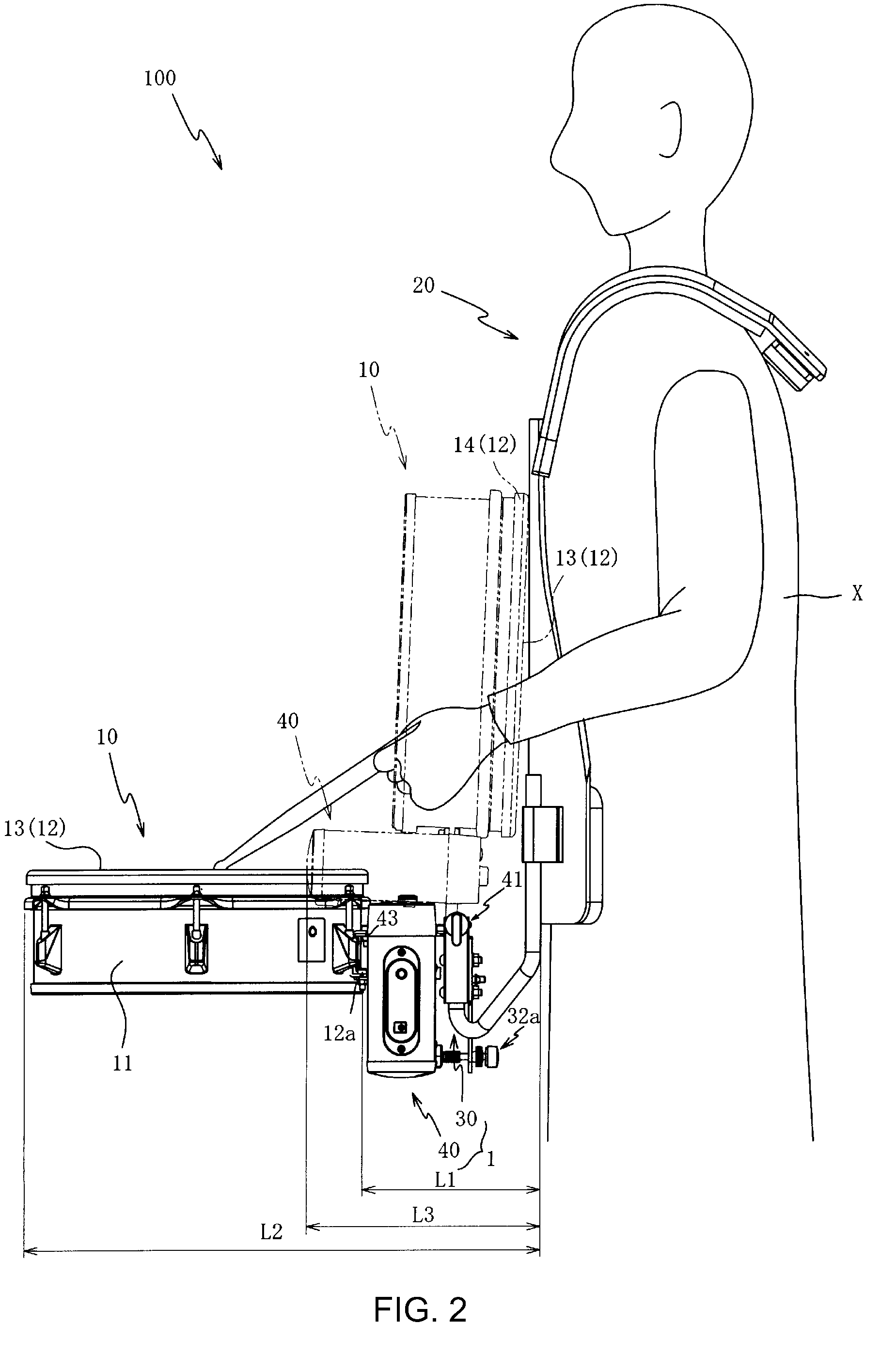
[0008]In addition, rigidity may be maintained because the case may be formed in a box form. Thus, the electronic percussion instrument may be stabilized and fastened to the case and the holding fixture. Moreover, the case may be arranged between the holding fixture supported on the body of the performer-user such that the case may be arranged closer to the performer-user than the electronic percussion instrument.
[0009]In various embodiments, an operating panel may be provided on the case. The operating panel may have a plurality of controls. In some embodiments, the plurality of controls may be arranged on the operating panel at a position lower than the striking surface of the pad. Therefore, because the operators may be arranged in a place where the performer-user's hand can easily reach, the operability of the operators may be improved. Accordingly, inadvertent striking of the operators may be mitigated. In addition, because the case may include an operating panel comprising a plurality of operators positioned lower than the striking surface of the pad, mistakes due to the performer-user inadvertently striking the case may be mitigated.
[0010]The electronic percussion instrument may be arranged such that a specified space is provided between the electronic percussion instrument and the holding fixture. This may effectively use space between the electronic percussion instrument and the holding fixture.
[0012]Because the printed circuit board may be attached to the housing and arranged perpendicular to the striking surface of the pad, damage to the printed circuit board may be mitigated. In other words, because the direction in which the vibrations produced by the striking of the pad and the printed circuit board are roughly perpendicular, the printed circuit board may be less likely to bend or warp, and thus damage to the printed circuit board from the vibrations may be reduced. Additionally, placing the case, which contains the electronic circuit for processing a signal produced by striking the pad, in the specified space may further effectively use the specified space provided between the electronic percussion instrument and the holding fixture.
[0014]Accordingly, because the instrument attachment member, the holding fixture attachment member, and the upper reinforcing plate may be configured as a single unit, the vibrations due to the striking of the pad may be transmitted to the holding fixture via the instrument attachment member, the upper reinforcing plate, and the holding fixture attachment member. Therefore, the relevant vibrations transmitted to the main body of the case containing the circuit board may be reduced to mitigate damage to the circuit board.

Problems solved by technology

Furthermore, the electronic percussion instrument 200 is not adapted to be fastened to a holding fixture worn by a user for marching and the like to allow a musical performance to be conducted while parading and performing.

Method used


Image

  • Operating devices and methods for electronic percussion instrument
  • Operating devices and methods for electronic percussion instrument
  • Operating devices and methods for electronic percussion instrument

Examples


Embodiment Construction

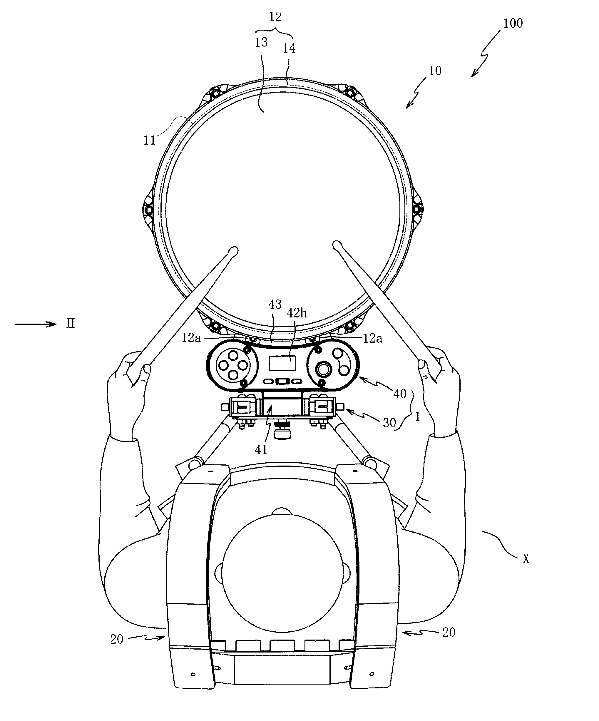
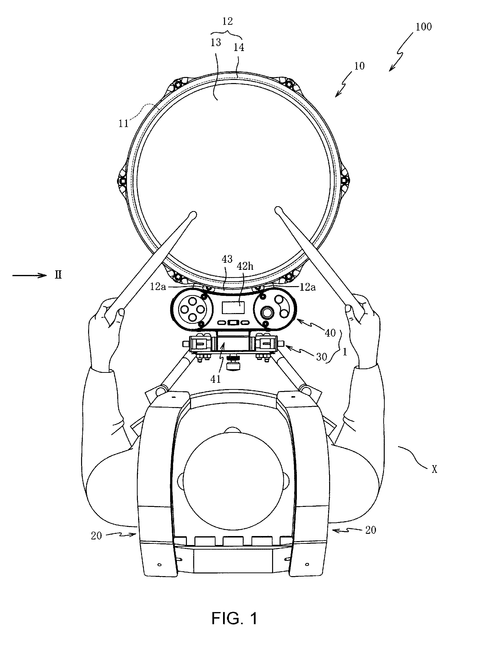
[0038]FIGS. 1 and 2 illustrate an electronic percussion instrument system 100 according to an embodiment of the present invention. The electronic percussion instrument system 100 may be a percussion instrument for marching, or the like. The electronic percussion instrument system 100 may comprise, but is not limited to, an electronic percussion instrument 10, a holding fixture 20, and an operating device 1.

[0039]In some embodiments, the electronic percussion instrument 10 may be for example, but not limited to, an electronic drum, or other electronic percussion instrument, which can be played with or otherwise performed upon using a drum stick, or the like.

[0040]The electronic percussion instrument 10 may comprise, but is not limited to, a main body 11 and a pad 12. The pad 12 may be arranged on a top surface of the main body 11. The electronic percussion instrument 10 may be arranged a specified distance L1 away from a performer-user X such that the pad 12 can be struck easily by t...


PUM


Abstract

An operating device for use with a musical instrument may allow for a supporting member configured to be supported by a user to be operatively connected to a percussion instrument with a case, which may contain an electronic circuit for processing a signal produced by striking a striking surface of the percussion instrument. The case may be arranged between the electronic percussion instrument and the supporting member. The case and the electronic percussion instrument may be configured to be moveable relative to the user.

Description

CROSS-REFERENCE TO RELATED PATENT APPLICATIONS[0001]Embodiments of the present invention relate to Japan Priority Application 2008-086180, filed Mar. 28, 2008 including the specification, drawings, claims, and abstract, and is incorporated herein by reference in its entirety and is a basis for priority.BACKGROUND OF THE INVENTION[0002]Japanese PCT translation H11-502640 discloses attaching an acoustic percussion instrument (e.g., a snare drum or a tomtom) to a holding fixture for marching and the like to allow a musical performance to be conducted while parading and performing.[0003]FIG. 8 of the present application illustrates an example of a previous type of electronic percussion instrument and case. As shown in FIG. 8, an electronic percussion instrument 200 has a head 213, which is formed with a flexible, permeable material, such as mesh and the like, a rim 214, which is arranged surrounding the head 213, and a case 210 containing an electronic circuit (not shown).[0004]However,...

Claims


Application Information

Patent Timeline
Patent Type & Authority Patents(United States)
IPC IPC(8): G10D1/02
CPCG10D13/024G10G5/005G10H1/32G10H2230/281G10H2230/365G10H2250/435G10D13/26G10D13/02
Inventor YOSHINO, KIYOSHIYAMANE, HIDEAKI
Owner ROLAND CORP
Learn More