Programmable window: a device for controlling the opacity of small-scale areas within a large scale transparent membrane

a technology of transparent membrane and opacity, applied in the field of environmental control and transparent displays, can solve the problems of no efficient method for regulating the amount of light that does pass through the display device, no work on pixellating these materials, and no work on achieving the effect of controlling the opacity of small areas and accurately and selectively controlling the amount of ligh

Active Publication Date: 2010-09-14
MASSACHUSETTS INST OF TECH
View PDF24 Cites 11 Cited by
  • Summary
  • Abstract
  • Description
  • Claims
  • Application Information

AI Technical Summary

Benefits of technology

[0006]The present invention provides for a device to control the opacity of small areas within a large transparent membrane. The transparent membrane of the present invention can be used both as a display panel incorporated onto any building facade or interior membranes, and for environmental control, namely as a tool to accurately and selectively control the amount of light that crosses small areas within the transparent envelope of an architectural volume. In both cases the device will display patterns that could both be looked at, and looked through.
[0007]When used as a display device on a whole / or part of a building's facade, the present invention's window sections will appear to be merely changing in opacity as viewed from the inside of the building, without blocking the outside view entirely. From an external viewpoint, the aggregate set of window panels could display discernible information. When used for environmental control, lighting levels will be controlled in a non-uniform way within an architectural space, leading to high degrees of accuracy. Also, while appearing well regulated on the inside, the image formed on the outside of the building might also contribute to its aesthetic characteristics.
[0008]The nature of the programmable window also allows for great freedom in choosing the “pixel” size and shape. This elemental unit which changes opacity within the window can be custom designed in order to be of any shape and size, so that an architect or designer can achieve the desired visual effects with great flexibility.

Problems solved by technology

The problem with most of the above is that the display device completely blocks light.
In the case of OLED display arrays, while light can travel across them, there is no efficient method for regulating the amount of light that does go through.
No work has been done in pixellating these materials to produce a large scale display and accurate environmental control device with architectural applications.

Method used


Image

  • Programmable window: a device for controlling the opacity of small-scale areas within a large scale transparent membrane
  • Programmable window: a device for controlling the opacity of small-scale areas within a large scale transparent membrane
  • Programmable window: a device for controlling the opacity of small-scale areas within a large scale transparent membrane

Examples


Embodiment Construction

[0043]While this invention is illustrated and described in a preferred embodiment, the invention may be produced in many different configurations. There is depicted in the drawings, and will herein be described in detail, a preferred embodiment of the invention, with the understanding that the present disclosure is to be considered as an exemplification of the principles of the invention and the associated functional specifications for its construction and is not intended to limit the invention to the embodiment illustrated. Those skilled in the art will envision many other possible variations within the scope of the present invention.

[0044]This invention focuses on applications to architecture, but the same device could be used in automobiles, marine vessels, aircrafts cameras, or any instrument that requires a selective and accurate regulation of light through a transparent membrane.

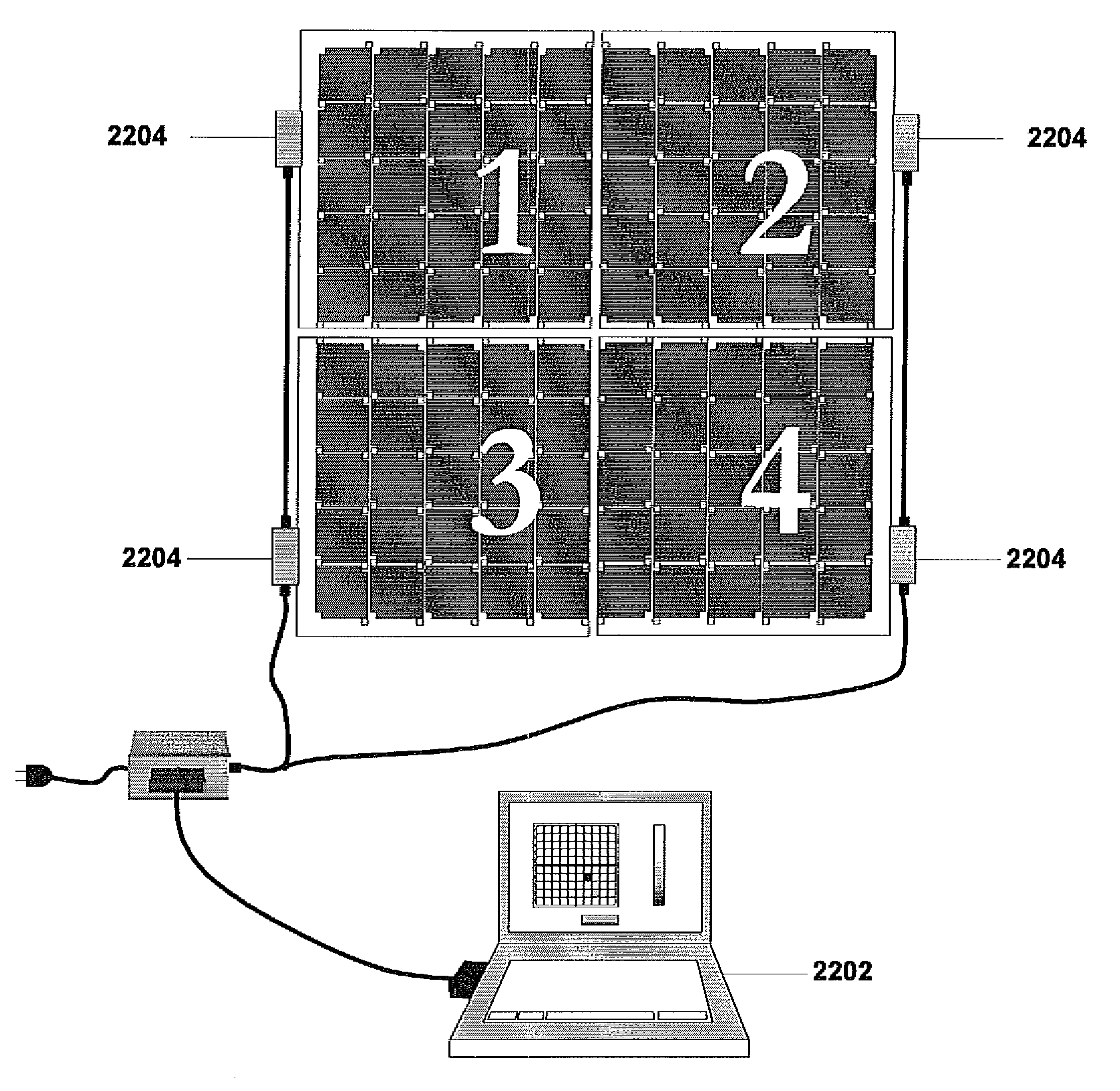
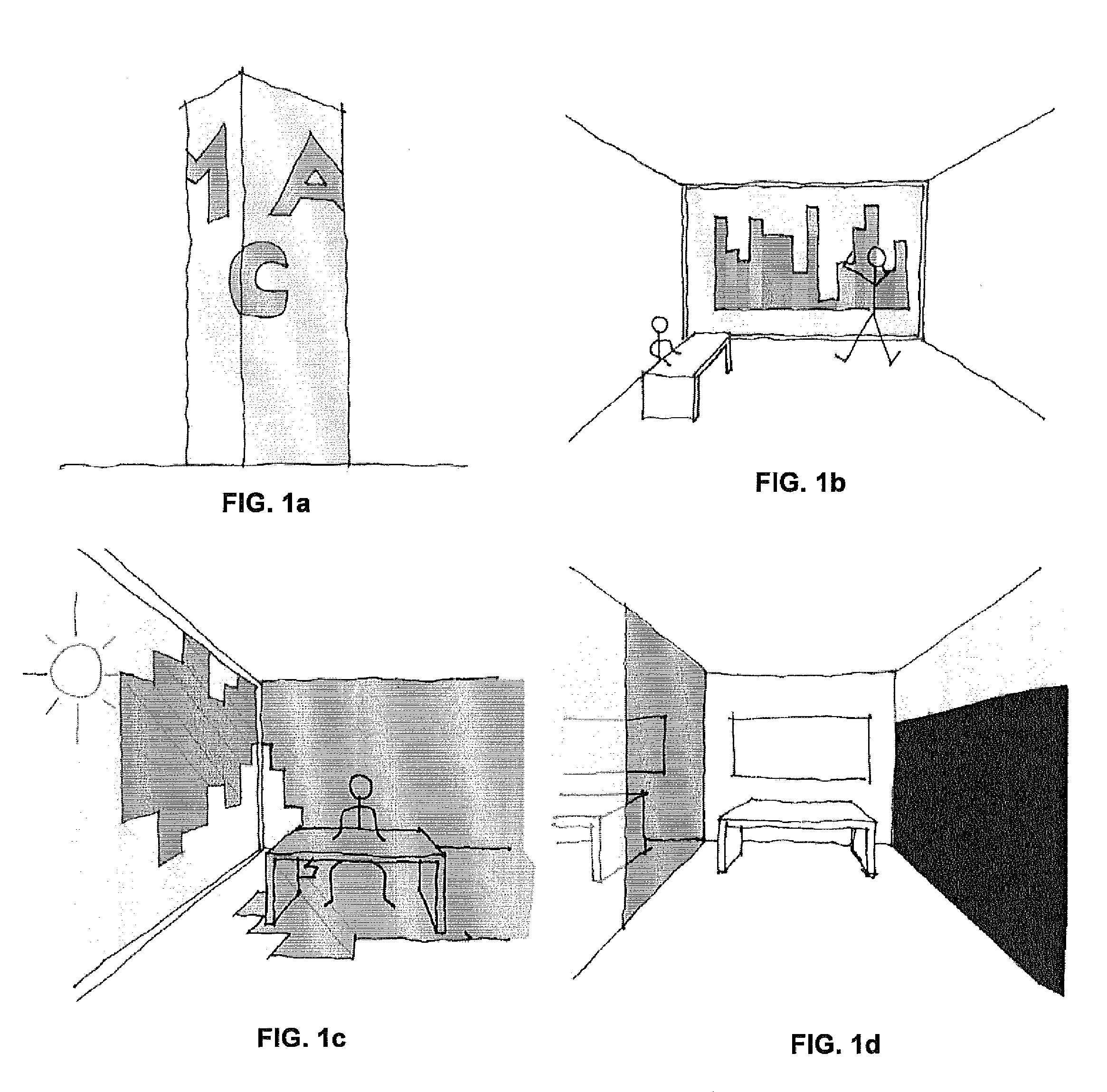
[0045]FIGS. 1a-d illustrates four main applications within architecture.

[0046]A) Large scale displa...


PUM


Abstract

Natural lighting profiles are affected in a building facade and internal transparent membrane using a transparent sheet having one or more pixel elements, wherein each of the pixel elements is capable of being driven to control opacity (by shading). A programmable controller is used to send control commands to control opacity of the pixel elements, wherein the percentage of light transmitted through the display panel forming part of the facade is controlled via the controller.

Description

BACKGROUND OF THE INVENTION[0001]1. Field of Invention[0002]The present invention relates generally to the field of environmental control and transparent displays. More specifically, the present invention is related to a programmable electronic device for controlling the opacity of small-scale areas within a large-scale transparent membrane for applications in architecture.[0003]2. Discussion of Prior Art[0004]The current range of possibilities for displaying information on a building-scale includes all forms of static and illuminated signs and panels, projections, as well as building-sized LED panels and one directional OLED display arrays. The problem with most of the above is that the display device completely blocks light. For instance, in the case of facade displays such as those in Times Square, N.Y., there is no view or natural light inside the buildings used as displays, and similarly in the case of window scale displays. In the case of OLED display arrays, while light can t...

Claims


Application Information

Patent Timeline
Patent Type & Authority Patents(United States)
IPC IPC(8): G02B26/00G02B5/30G09G3/34
CPCE04B1/00G09F19/22G09G3/34G09F19/226G09G2300/06G02F1/172G09G2310/0208G09G2310/0267G09G2320/0209G09G2300/088G09F19/227
Inventor RATTI, CARLOBIDERMAN, ASSAFRAMOS, MARTIN
Owner MASSACHUSETTS INST OF TECH
Why Eureka
Try Eureka