
Automatic opacity detection system for cortical cataract diagnosis

Inactive Publication Date: 2011-04-21
AGENCY FOR SCI TECH & RES +2
View PDF3 Cites 7 Cited by
  • Summary
  • Abstract
  • Description
  • Claims
  • Application Information

AI Technical Summary

Benefits of technology

[0011]Since embodiments of the system are automatic, preferred embodiments make it possible to diagnose cortical cataracts more objectively, and at the same time to save the workload of clinical doctors.
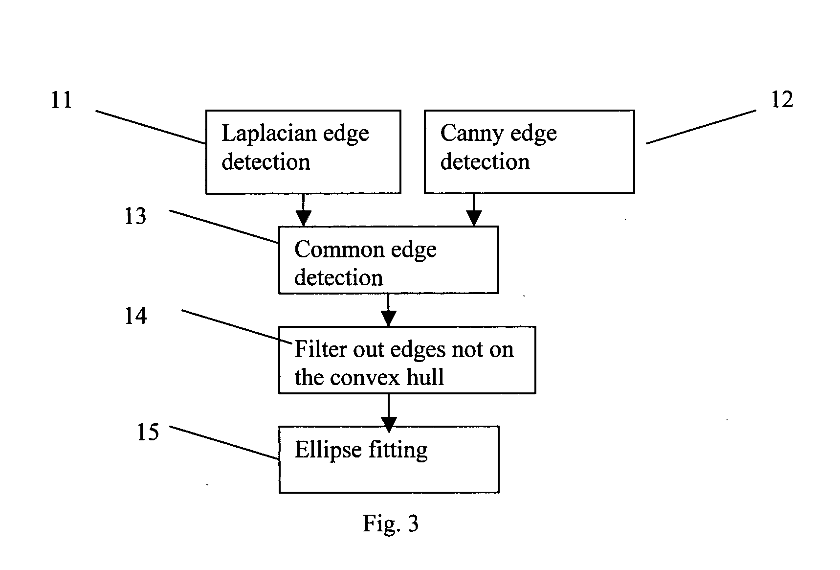
[0012]The region of interest (ROI) detection preferably includes detection of edges (i.e. borders of regions with different intensities) within the image, generation of a convex hull including the edges, and then fitting of an ellipse to the convex hull. Edges within the pupil are unlikely to lie on the convex hull, and, if not, are not taken into account during the ellipse fitting. This may make it possible achieve a robust result in the case of severe cataracts.
[0019]Optionally a plurality of identification algorithms of types (a) to (d) are performed. The results of the algorithms are combined in such a way that edges and opacity centers identified by identification algorithm(s) of type (a) and (b) are combined, but so as to reduce the estimated effects of edges and opacity centers identified by identification algorithm(s) of types (c) and (d). For example, the results of an identification algorithm of type (c) or (d) can be used to generate compensation data indicative of expected opacity, the compensation data being used to reduce identified opacity within the image, such as by subtracting the compensation data from data obtained by identification algorithm(s) of types (a) and / or (b).

Problems solved by technology

Cataracts are the leading cause of blindness worldwide.
However, studies have shown that the measurement is still not identical among graders, nor for the same grader at different times [5].
The measurement of the area of opacity is time-consuming as well.
Opacity detection by global thresholding is often inaccurate due to non-uniform illumination of the lens.
This contrast based approach is unsatisfactory, however, when opacities are so dense that the contrast in the opacified areas is no longer high.

Method used


Image

  • Automatic opacity detection system for cortical cataract diagnosis
  • Automatic opacity detection system for cortical cataract diagnosis
  • Automatic opacity detection system for cortical cataract diagnosis

Examples


Embodiment Construction

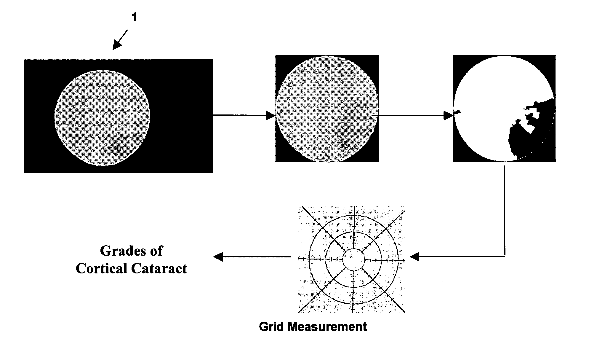
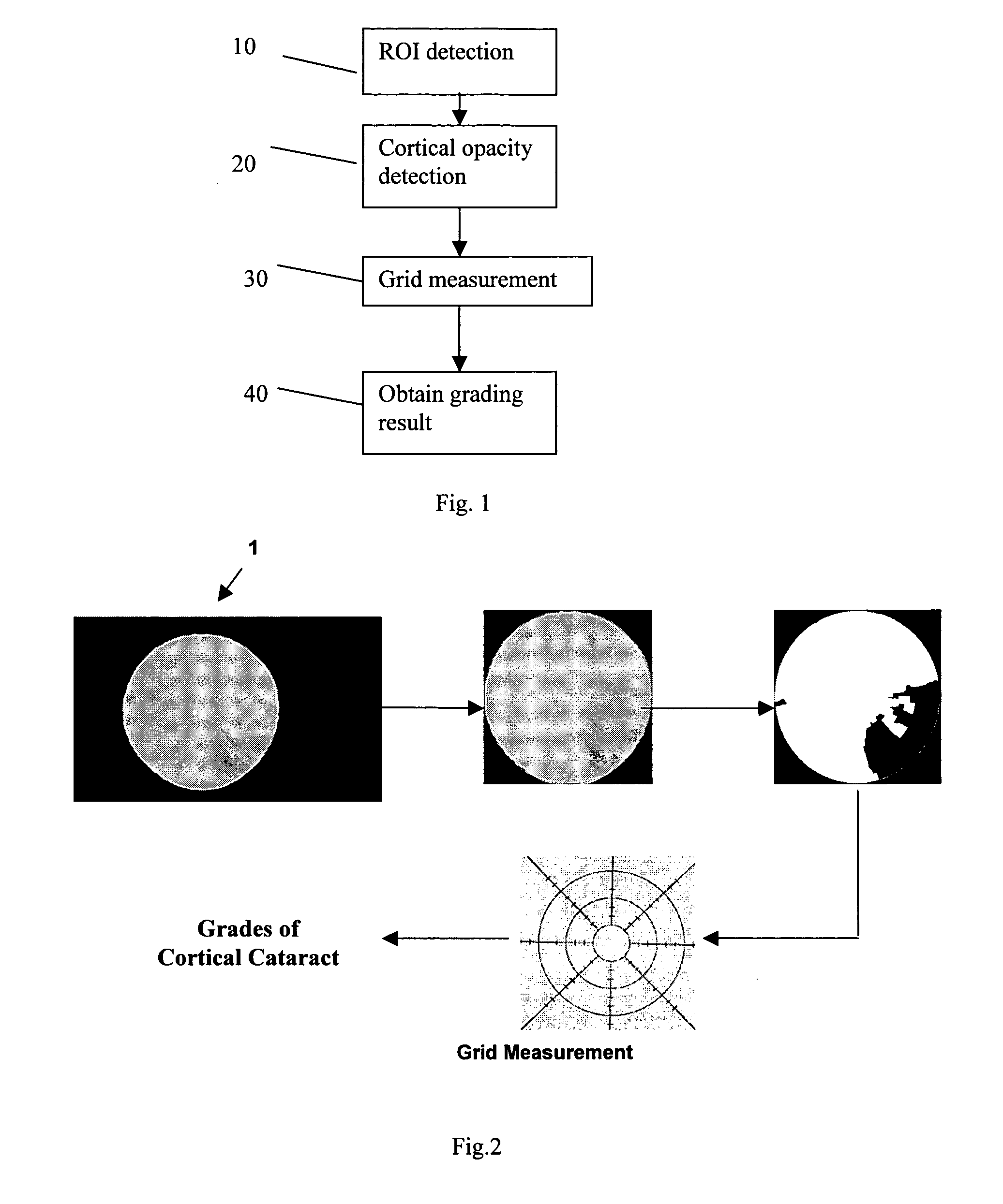
[0036]Referring to FIGS. 1 and 2, the steps are illustrated of a software system which is an embodiment of the present invention, and which extracts from lens images the cortical opacity, and grades it. FIG. 1 is a flow diagram of these steps, while FIG. 2 shows the steps schematically, with reference to images representing the results of each step of the process. Corresponding steps of FIGS. 1 and 2 are indicated by the same reference numerals.

[0037]The input to the embodiment is an optical image 1, containing a light approximately-circular region which is a pupil, surrounded by a dark border. Opacity is indicated by the darkened region of this pupil.

(i) ROI detection (step 10)

[0038]A first step of the method (step 10) is ROI Detection, the sub-steps of which are illustrated in FIG. 3. In a first sub-step 11, the original image 1 is filtered by a Laplacian edge-detection filter and thresholded to obtain the Laplacian edges (a well know algorithm).

[0039]In a second sub-step 12, cann...


PUM


Abstract

A method performed by a computer system for detecting opacity in an image of the lens of an eye. The method includes detecting a region of interest in a picture of the lens, and processing the region of interest to produce a modified image using an algorithm which emphasizes opacity associated with a cortical cataract relative to opacity caused by other types of opacity, such as opacity caused by posterior sub-capsular cataracts (PSC). The modified image may be used for grading the level of cortical opacity, by measuring, in the modified image, the proportion of opacity in at least one area of the region of interest.

Description

FIELD OF THE INVENTION[0001]The present invention relates to an automatic opacity detection system, having method and apparatus aspects. The system can be used to obtain a grading value for opacity due to cortical cataracts (“cortical opacity”), for example to perform cortical cataract diagnosis.BACKGROUND OF THE INVENTION[0002]Cataracts are the leading cause of blindness worldwide. It has been reported that 47.8% of global blindness is caused by cataracts [1], and 35% of Singapore Chinese people over 40 years old are reported to have cataracts [2]. A cataract is due to opacity or darkening of crystalline lens. According to some studies [3]-[4], the most prevalent type of cataracts are cortical cataracts which begin as whitish, wedge-shaped opacities or streaks on the outer edge cortex (or periphery) of the lens, and as they slowly progress, the streaks extend to the center and interfere with light passing through the center of the lens. By contrast, a sub-capsular cataract starts a...

Claims


Application Information

Patent Timeline
IPC IPC(8): G06K9/00
CPCG06T7/0012G06T7/403G06T2207/30041G06T2207/20104G06T7/60G06T7/44
Inventor LI, HUIQILIM, JOO HWEELIU, JIANGKO, LI LIANGWONG, WING KEE DAMONWONG, TIEN YIN
Owner AGENCY FOR SCI TECH & RES
Learn More