Secure optical communication

a technology of optical communication and communication method, applied in the field of secure optical communication, can solve problems such as difficulty for a person wishing to eavesdrop on a communication

Active Publication Date: 2010-09-14
BRITISH TELECOMM PLC
View PDF151 Cites 27 Cited by
  • Summary
  • Abstract
  • Description
  • Claims
  • Application Information

AI Technical Summary

Benefits of technology

[0016]The times at which data is modulated on to (carrier) signals will preferably be chosen such that when signal copies return to the first location, a modulated signal is combined with a signal having the same but unmodulated irregular components. That is, for each pair of signal copies that are combined, one signal of the pair will be modulated, whereas the other copy of the pair will not be modulated. The data will preferably be modulated in burst mode, such that between periods when data is being modulated, there are quiet intervals during which data is not being modulated. Such quiet intervals will allow carrier signals to return to the first location without modulation, in order to

Problems solved by technology

Because the output signals have an irregular component, and because the data to be communicated from the second location to the first location is mixed with the

Method used


Image

  • Secure optical communication
  • Secure optical communication

Examples


Embodiment Construction

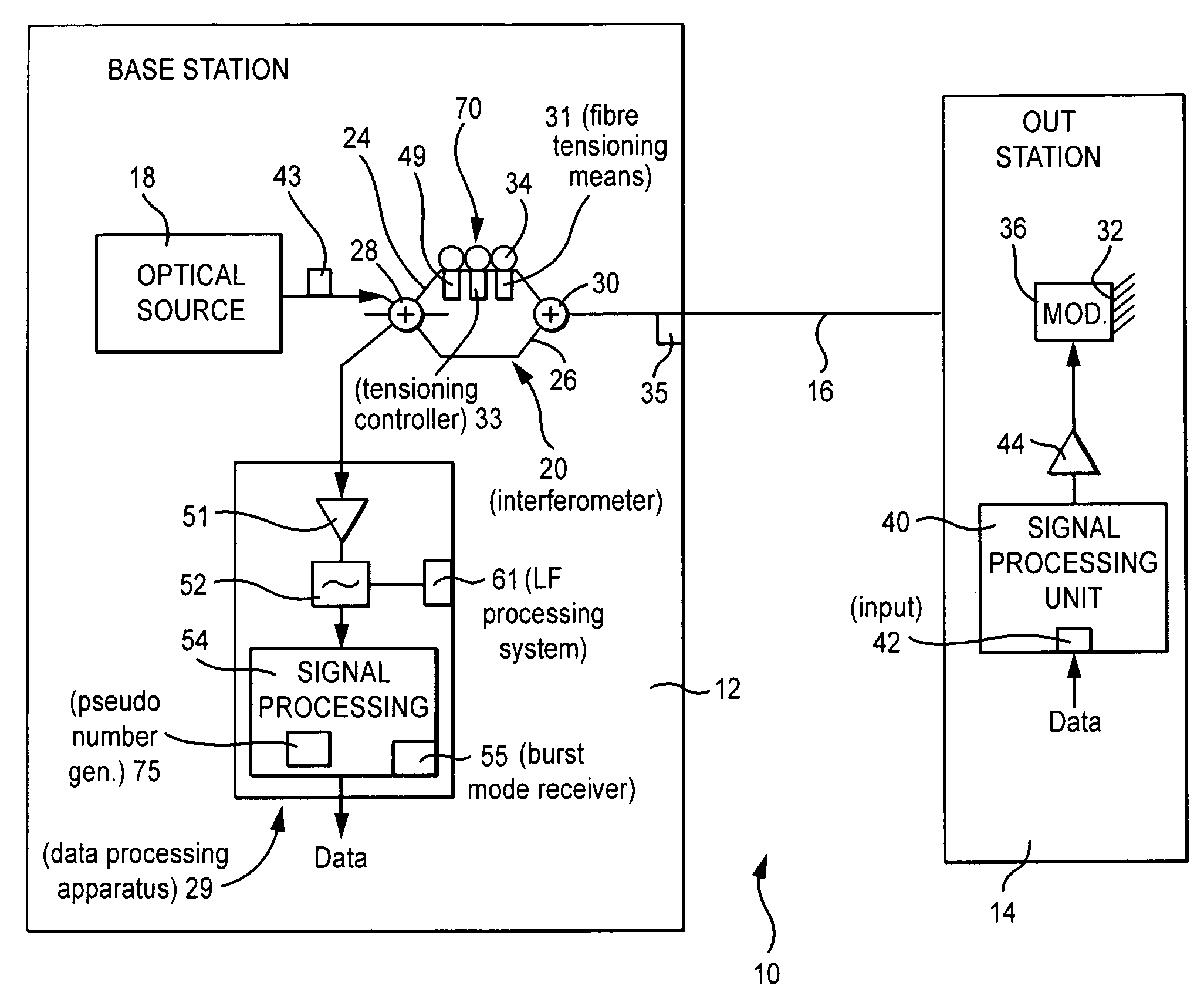
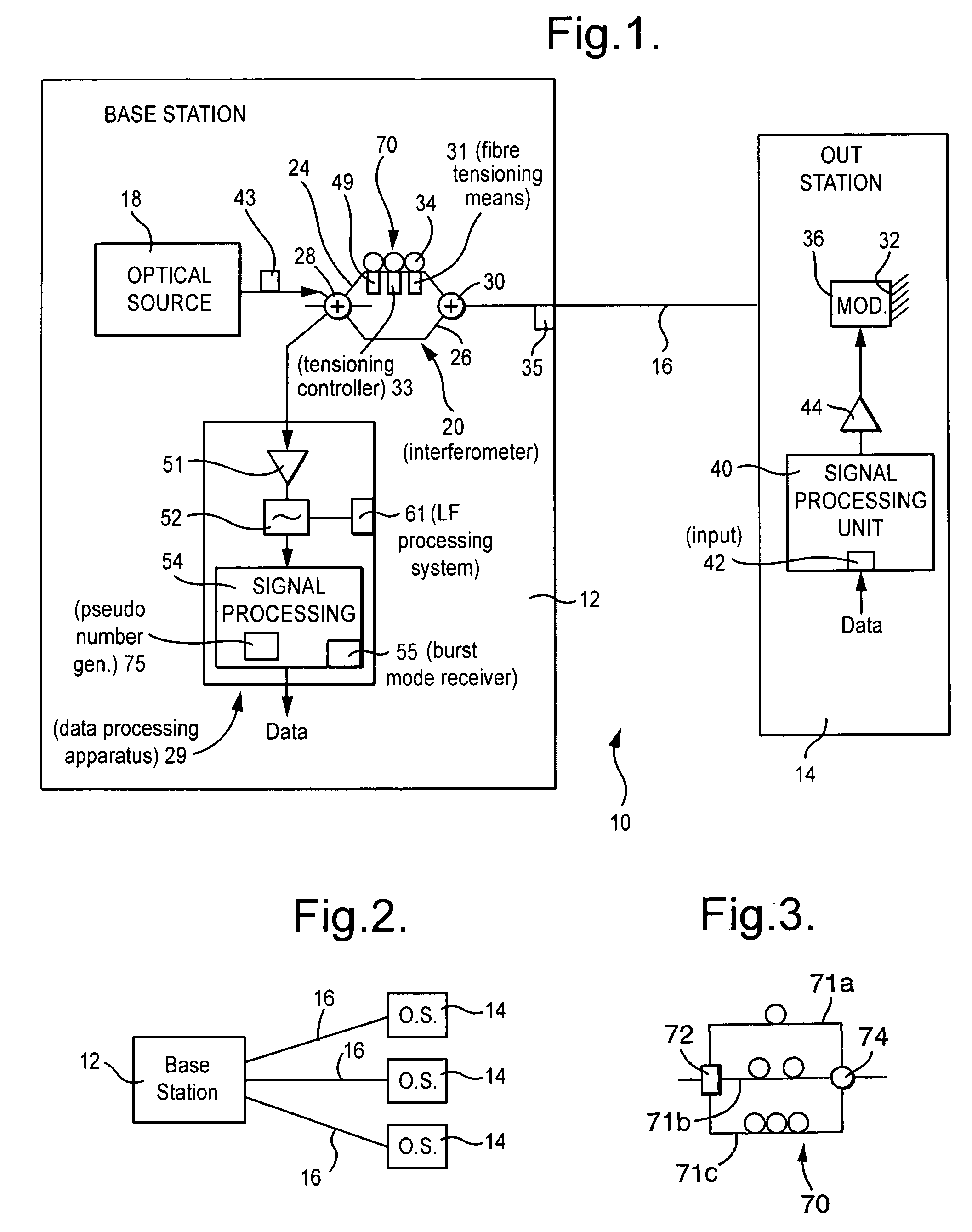
[0023]FIG. 1 shows a secure communications system in which a base station 12 can receive data from an outstation 14, over an optical communications link 16 extending between the base station 12 and the outstation 14. The base station 12 includes an optical source 18 with a short coherence time. Wavetrain portions also known as carrier signals (hereinafter referred to as signals) from the optical source 18 are fed to an interferometer stage 20, here a Mach-Zehender interferometer having a first path 24 and a second path 26. The interferometer 20 includes first coupling stage 28 for coupling optical radiation between the optical source 18, the first and second paths 24, 26, and data processing apparatus 29. For light travelling in a forward direction, that is, towards the outstation 14, the first coupling stage 28 acts as a directional power (intensity) splitter, channeling light from the optical source 18 to each of the paths 24, 26, the power to each path being shared in a predeterm...


PUM


Abstract

A secure optical communication scheme uses differential delay D in an unbalanced Mach-Zehender interferometer to provide two copies of the optical source signal at a remote phase modulator separated in time by D. As D is much bigger than the coherence time source, the two copies of the signal are effectively uncorrelated. Both signals are phase-modulated by the remote sender's data and returned to the unbalanced interferometer. The phase modulator will be converted into amplitude modulation by the action of the interferometer.

Description

[0001]This application is the US national phase of international application PCT / GB2004 / 004169 filed 29 Sep. 2004 which designated the U.S. and claims benefit of GB 0322859.0, dated 30 Sep. 2003, the entire content of which is hereby incorporated by reference.BACKGROUND[0002]1. Technical Field[0003]The present invention relates to a method and apparatus for the communication of data, in particular for the secure communication of data.[0004]2. Related Art[0005]It is known to encrypt data in order to reduce the risk of unauthorised access to the data when the data is being transmitted over a link. However, such encryption methods can be complicated or processor intensive.BRIEF SUMMARY[0006]According to one aspect of the present invention, there is provided a method of communicating between a first location and a second location, the method including the steps of: at the first location, generating output signals having an irregular component, and copying the output signals at least in ...

Claims


Application Information

Patent Timeline
IPC IPC(8): H04B10/00H04B10/2587H04B10/50H04K1/00
CPCH04B10/2587H04B10/505H04K1/00
Inventor SIKORA, EDMUND S RHEALEY, PETER
Owner BRITISH TELECOMM PLC
Why Eureka
Try Eureka