Decorative pole and pedestal stabilizing container
a technology of decorative poles and pedestals, applied in the field of decorative poles, can solve the problems of trip hazards, incompatibility of base stands with home or office décor, and too small or too light to offer sufficient stability
- Summary
- Abstract
- Description
- Claims
- Application Information
AI Technical Summary
Benefits of technology
Problems solved by technology
Method used
Image
Examples
embodiment
Preferred Embodiment
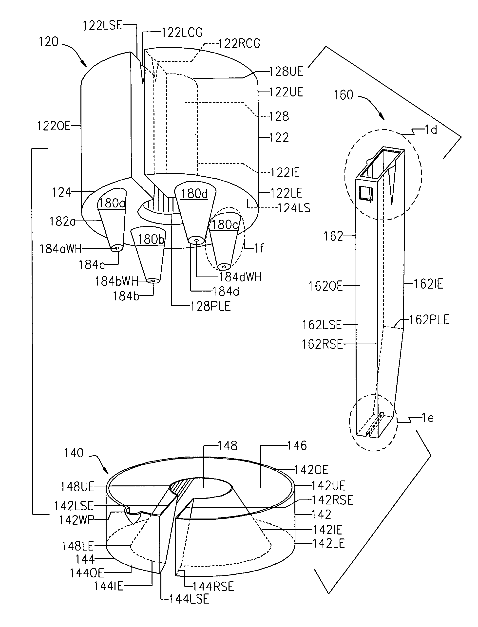
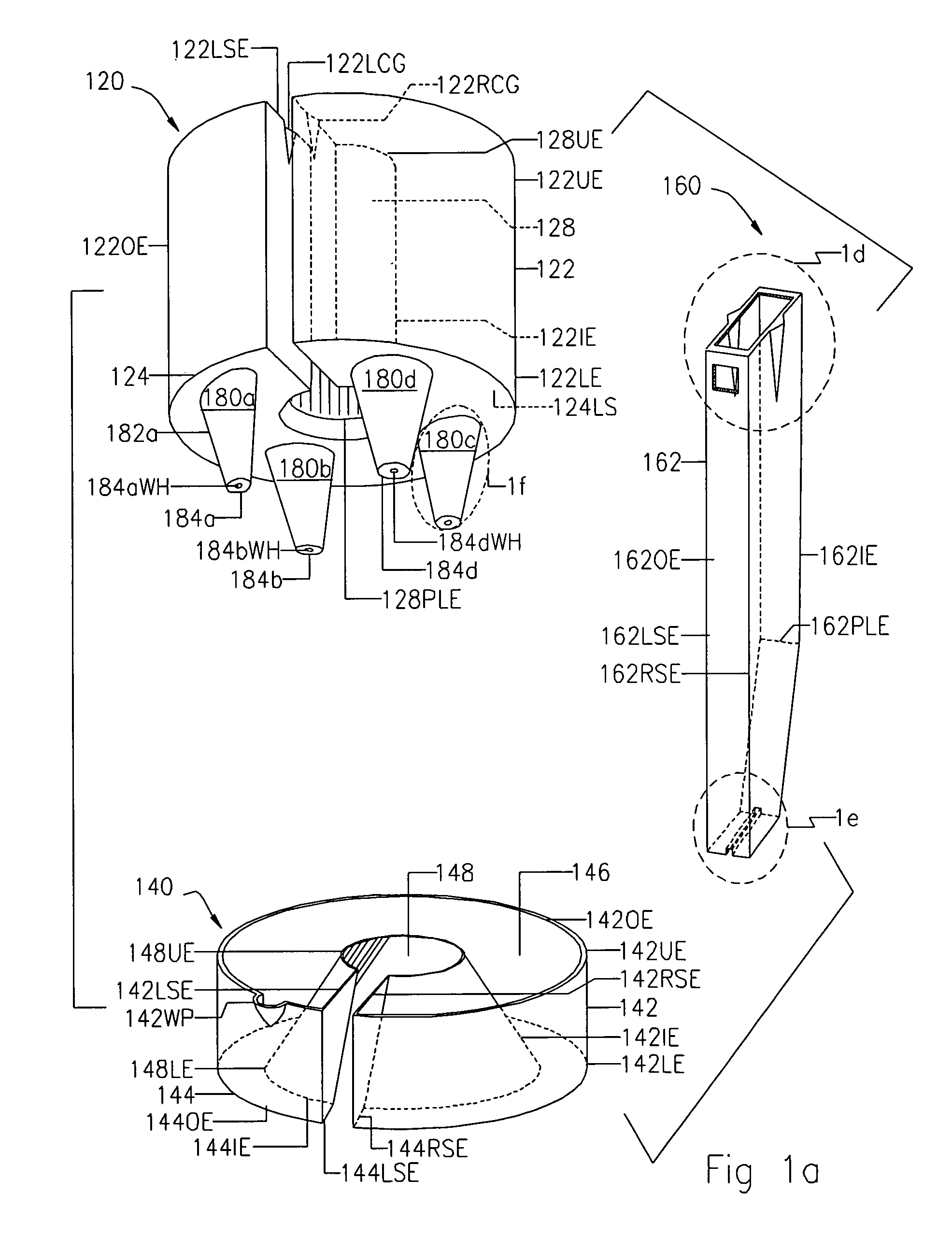
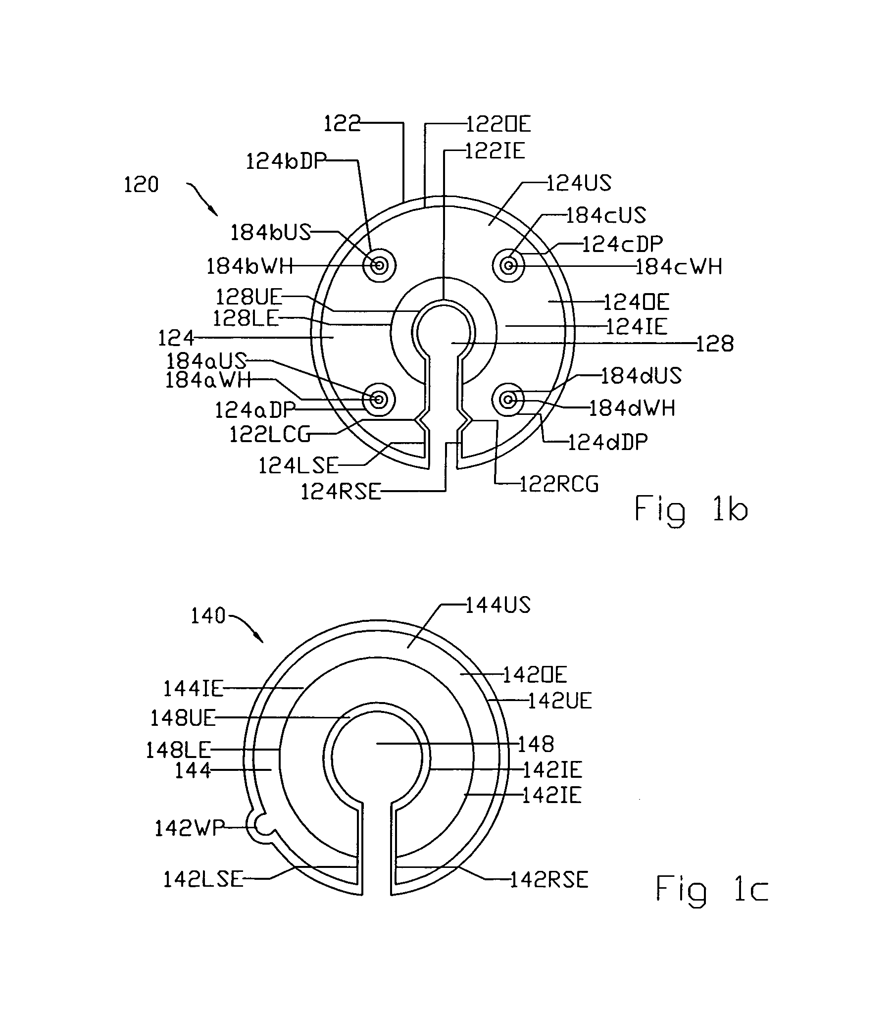
FIGS. 1a-1g
[0083]A container of the preferred embodiment, as shown in FIGS. 1a through 1g of the patent drawings, operates in the following manner.
[0084]To assemble the container, the user first lifts the empty lower reservoir section 140 and orients lower fixture void or base void 148 to align with pole 12 of freestanding fixture such as floor lamp 10. Then the user moves the empty lower reservoir section 140 toward and around pole 12 so that pole 12 is now in the center of lower fixture void or base void 148 of lower reservoir section 140. Thereafter, the user sets down the empty lower reservoir section 140 such that lower fixture void or base void 148 substantially surrounds a base stand or pedestal 14 of freestanding fixture such as floor lamp 10.
[0085]Next the user lifts the empty upper planter section 120 and orients upper fixture void or pole void 128 to align with pole 12 of a freestanding fixture such as floor lamp 10. Then the user moves the empty uppe...
second embodiment
Alternate Second Embodiment
FIGS. 2a, 2b
[0092]The alternate second embodiment includes an upper planter section 220 with a plurality of tri-sectional circumferentially shaped circumferentially arrayed stands 280a, 280b, and 280c (bottom perspective view and top view) shown in FIGS. 2a and 2b, respectively, a lower reservoir section 140 (top perspective shown in FIG. 1a, and a wedge section 160 (top perspective view) shown in FIG. 1a.
[0093]All aspects of the second embodiment are the same as the preferred embodiment except for the shape and configuration and array of a plurality of circumferentially arrayed stands 280a, 280b, and 280c being tri-sectional circumferentially shaped instead of conical shaped. In all other aspects, the second embodiment is similar in structure as the preferred embodiment of the present invention.
third embodiment
Alternate Third Embodiment
FIGS. 3a, 3b
[0094]The alternate third embodiment includes an upper planter section 320 with a plurality of tetra-sectional circumferentially shaped circumferentially arrayed stands 380a, 380b, 380c, and 380d (bottom perspective view and top view) shown in FIGS. 3a and 3b, respectively, a lower reservoir section 140 (top perspective shown in FIG. 1a, and a wedge section 160 (top perspective view) shown in FIG. 1a.
[0095]All aspects of the third embodiment are the same as the preferred embodiment except for the shape and configuration and array of a plurality of circumferentially arrayed stands 380a, 380b, 380c, and 380d being tetra-sectional circumferentially shaped instead of conical shaped. In all other aspects, the third embodiment is similar in structure as the preferred embodiment of the present invention.
PUM
 Abstract
Description
Claims
Application Information
 - R&D
- Intellectual Property
- Life Sciences
- Materials
- Tech Scout
- Unparalleled Data Quality
- Higher Quality Content
- 60% Fewer Hallucinations
Browse by: Latest US Patents, China's latest patents, Technical Efficacy Thesaurus, Application Domain, Technology Topic, Popular Technical Reports.
© 2025 PatSnap. All rights reserved.Legal|Privacy policy|Modern Slavery Act Transparency Statement|Sitemap|About US| Contact US: help@patsnap.com


