Gas turbine engine having slim-line nacelle

a gas turbine engine and nacelle technology, applied in the direction of machines/engines, mechanical equipment, transportation and packaging, etc., can solve the problems of increased weight and drag

Active Publication Date: 2010-09-21
RTX CORP
View PDF50 Cites 28 Cited by
  • Summary
  • Abstract
  • Description
  • Claims
  • Application Information

AI Technical Summary

Problems solved by technology

Disadvantageously, the relatively large size of the nacelle results in increased weight and drag that may offset the propulsive efficiency achieved by high bypass turbofan engines.

Method used


Image

  • Gas turbine engine having slim-line nacelle
  • Gas turbine engine having slim-line nacelle
  • Gas turbine engine having slim-line nacelle

Examples


Embodiment Construction

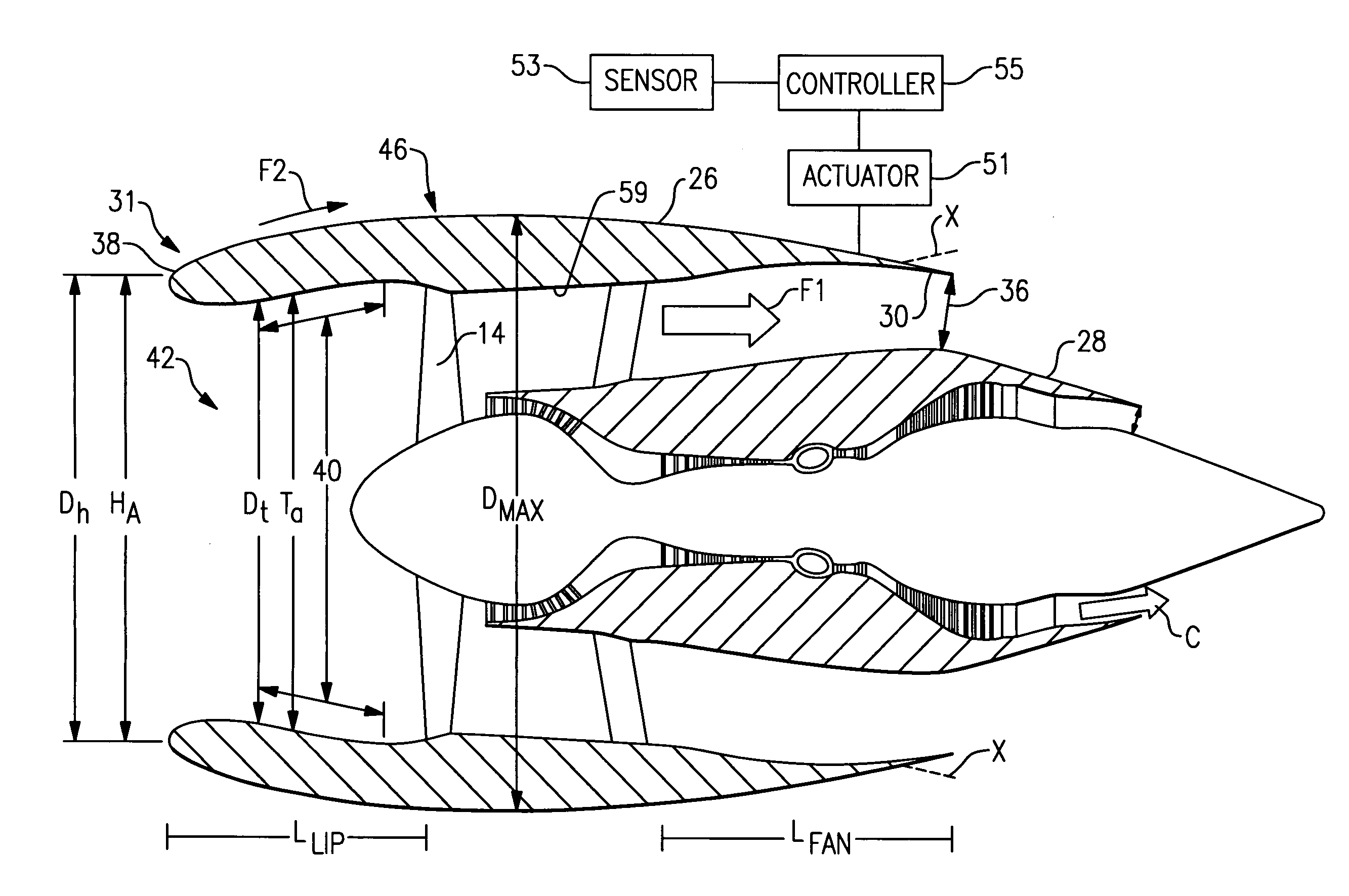
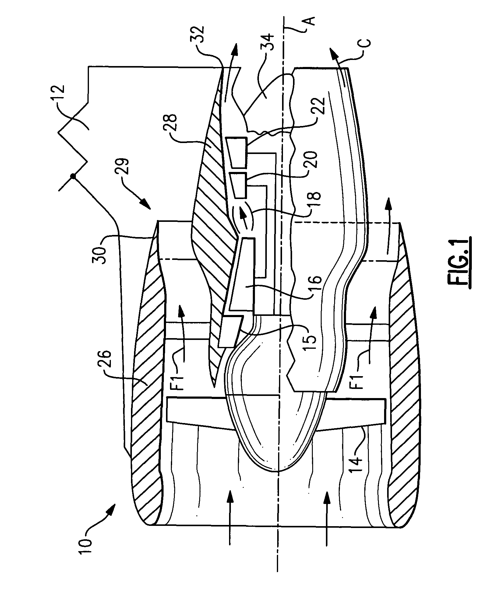
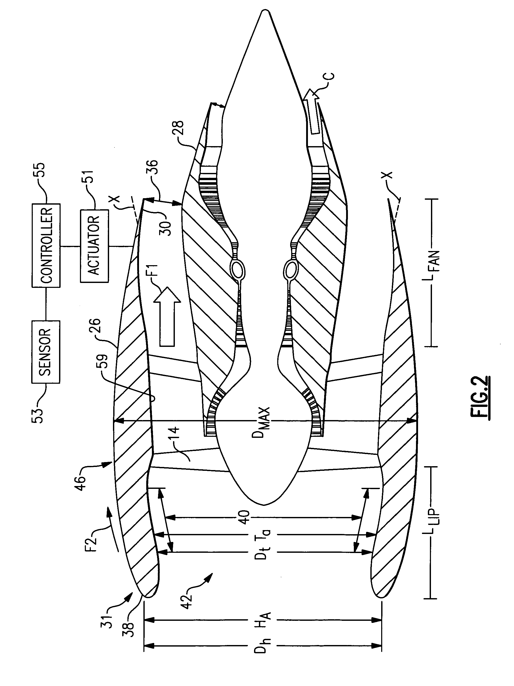
[0015]Referring to FIG. 1, a gas turbine engine 10 typically includes (in serial flow communication) a fan 14, a low pressure compressor 15, a high pressure compressor 16, a combustor 18, a high pressure turbine 20 and a low pressure turbine 22. During operation, air is pressurized in the compressors 15, 16 and mixed with fuel in the combustor 18 for generating hot combustion gases. The hot combustion gases flow through the high and low pressure turbines 20, 22 which extract energy from the hot combustion gases. The high pressure turbine 20 powers the high pressure compressor 16 through a shaft defined therebetween, and the low pressure turbine 22 powers the fan 14 and the low pressure compressor 15 through another shaft defined therebetween. The invention is not limited to the two spool axial gas turbine architecture described and may be used with other architectures, such as a single spool axial design, a three spool axial design and other architectures.

[0016]The gas turbine engin...


PUM

PropertyMeasurementUnit
areaaaaaaaaaaa
angleaaaaaaaaaa
energyaaaaaaaaaa

Abstract

A nacelle assembly for a gas turbine engine includes a nacelle, a variable area fan nozzle, a sensor that detects a windmilling condition and a controller that communicates with the sensor. The variable area fan nozzle is moveable between a first position having a first discharge airflow area and a second position having a second discharge airflow area greater than the first discharge airflow area in response to detecting the windmilling condition.

Description

BACKGROUND OF THE INVENTION[0001]This invention generally relates to a gas turbine engine, and more particularly to a nacelle for a turbofan gas turbine engine.[0002]In an aircraft gas turbine engine, such as a turbofan engine, air is pressurized in a compressor and mixed with fuel in a combustor for generating hot combustion gases. The hot combustion gases flow downstream through turbine stages that extract energy from the gases. In a two spool gas turbine engine, a high pressure turbine powers the high pressure compressor, while a low pressure turbine powers a fan disposed upstream of the compressor and a low pressure compressor.[0003]Combustion gases are discharged from the turbofan engine through a core exhaust nozzle, and fan air is discharged through an annular fan exhaust nozzle defined at least partially by a nacelle surrounding the core engine. A majority of propulsion thrust is provided by the pressurized fan air which is discharged through the fan exhaust nozzle, while th...

Claims


Application Information

Patent Timeline
Patent Type & Authority Patents(United States)
IPC IPC(8): F02K1/00
CPCF02K1/06F02K1/15F02K3/06F02K1/165Y10T29/4932F05D2270/09Y02T50/671F05D2270/092F05D2260/80Y10T137/0536Y02T50/60
Inventor MORFORD, STEPHEN A.LARKIN, MICHAEL J.
Owner RTX CORP
Why Eureka
Try Eureka