Radial spring latch apparatus and methods for making and using same

a technology of latching and radial springs, which is applied in the direction of rod connections, couplings, borehole/well accessories, etc., can solve the problems of high specific forces required to operate mechanisms including spring collets, and the sleeve elements of the latching sleeve do not lend themselves to shifting sleeve elements, so as to prevent fluid loss or fluid intermixing, the effect of high locking for

Active Publication Date: 2010-09-21
BAKER HUGHES INC
View PDF28 Cites 22 Cited by
  • Summary
  • Abstract
  • Description
  • Claims
  • Application Information

AI Technical Summary

Benefits of technology

[0008]The present invention provides a locking apparatus which utilizes a natural spring constant of a protrusion or a hoop or ring engaging a grooved surface to create a latching force of a desired magnitude. The locking apparatus of this invention is capable of achieving a higher locking force, is capable of being stiffer than slotted spring apparatuses, and is capable of forming a fluid tight seal for preventing fluid loss or fluid intermixing.

Problems solved by technology

These slotted sleeve elements do not lend themselves to shifting sleeve elements that must seal out fluids and / or avoid debris accumulation.
Additionally, the specific forces required to operate mechanisms including spring collets are often high and require a separate shear element mechanism for initiation.

Method used


Image

  • Radial spring latch apparatus and methods for making and using same
  • Radial spring latch apparatus and methods for making and using same
  • Radial spring latch apparatus and methods for making and using same

Examples


Embodiment Construction

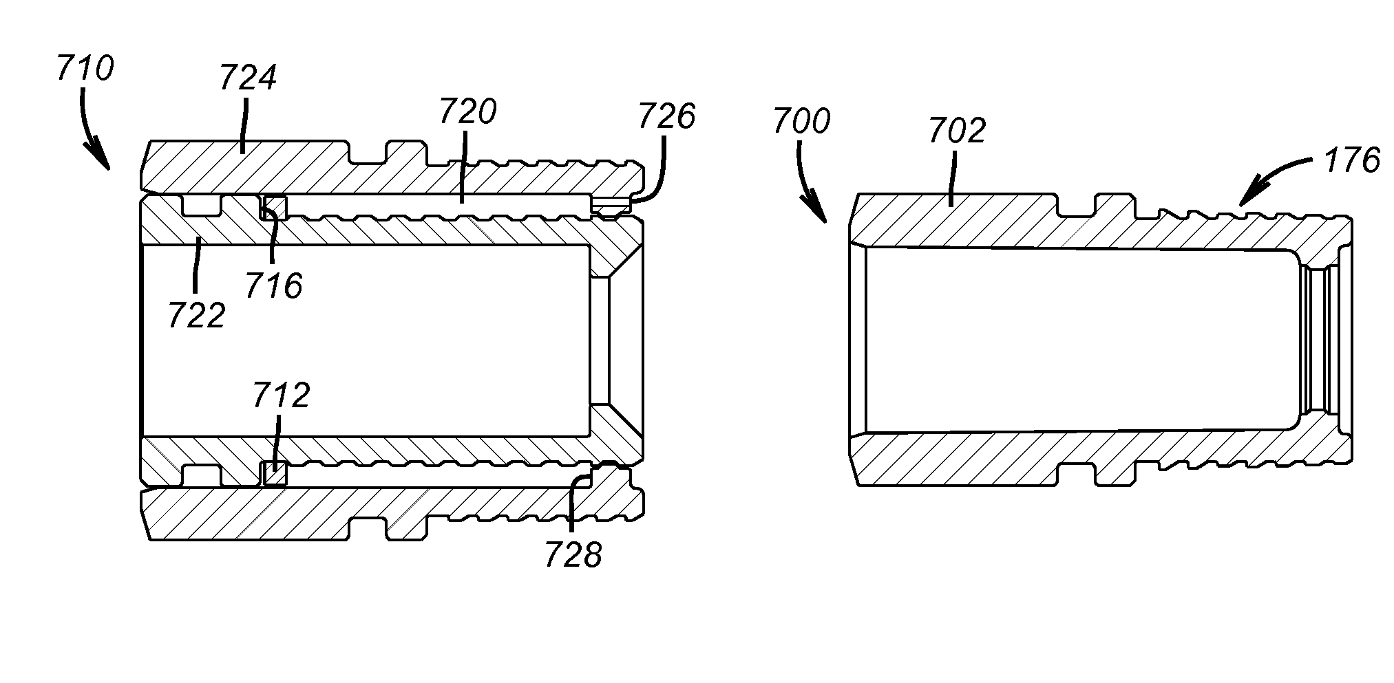
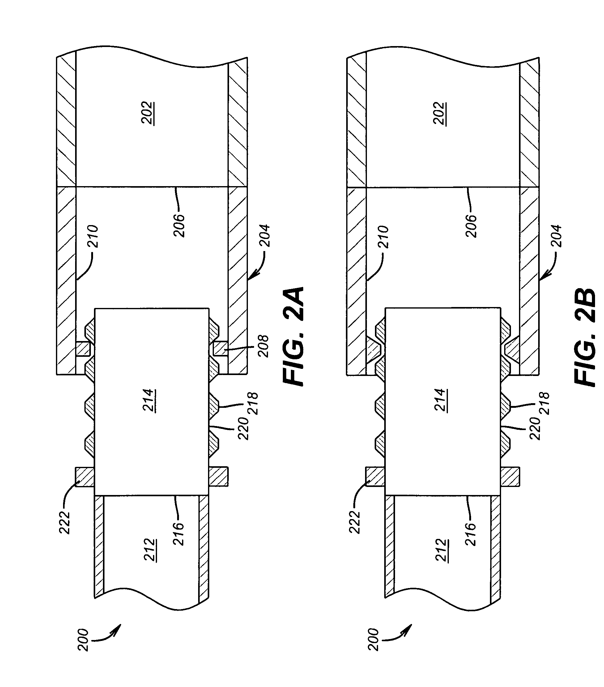
[0022]The inventors have found that a new extension / retraction apparatus can be constructed where the locking force is achieved via the interaction of sleeve deployed detents and detent engaging elements disposed on opposed surfaces of an inner sleeve and an outer sleeve or on opposed surfaces of an outer sleeve and an outer sleeve mount. The apparatus extends or retracts in a ratchet-like motion in an axial or in and out direction due to application of an external force acting on the proximal or distal end of the inner sleeve sufficient to step-wise extend or retract the inner sleeve relative to the outer sleeve. The ratchet-like motion results from the interaction of detents or bumps on the outer surface of a sleeve and a detent engaging element on the inner surface of a second sleeve or a sleeve mounting assembly. The interaction between the detents and the detent engaging element cause the detents and / or the detent engaging element to undergo radial expansion or contraction as t...


PUM


Abstract

New locking connector assemblies and telescoping extension / retraction assemblies are disclosed that operate on the natural spring rate constraints of radial protrusions or radially constrained rings as they interact with engaging members to provide the locking force and permit the connector and extension retraction assemblies to be engage and disengaged or extended and retracted.

Description

BACKGROUND OF THE INVENTION[0001]1. Field of the Invention[0002]The present invention relates to a locking apparatus and a method for using the locking apparatus, where the locking apparatus is ideally suited for oil field applications such as drilling, completions, and / or production applications.[0003]More particularly, the present invention relates to a latching or locking apparatus including a first member and a second member, where the first member includes an inner surface having an inwardly extending protrusion and the second member includes an outer surface having a plurality of a grooves and a bumps and where the second member is designed to slide into the first member so that the protrusion of the first member lockingly engages the bumps and grooves of the second member. The present invention also relates to methods for making and using same.[0004]2. Description of the Related Art[0005]The mechanisms currently deployed during drilling, completions, and / or production operati...

Claims


Application Information

Patent Timeline
Patent Type & Authority Patents(United States)
IPC IPC(8): E21B17/07
CPCE21B17/04F16L27/12E21B17/07Y10T403/32451F16L27/1273E21B17/046E21B23/02
Inventor HARVEY, PETER R.JOHNSON, MICHAEL H.XU, YANG
Owner BAKER HUGHES INC
Why Eureka
Try Eureka