Paper sheet conveyance method and paper sheet conveyance device with common blower duct

Inactive Publication Date: 2010-09-21
MARS ENG
View PDF6 Cites 5 Cited by
  • Summary
  • Abstract
  • Description
  • Claims
  • Application Information

AI Technical Summary

Benefits of technology

[0034]In the method and the equipment of the present invention, the open/close valve of the blower duct, into which the sheet-shaped member has been fed, is preferentially opened so as to feed the sheet-shaped member into t

Problems solved by technology

For example, in an extensive game hall, the conventional equipment must be large in size and a running cost for driving the b

Method used


Image

  • Paper sheet conveyance method and paper sheet conveyance device with common blower duct
  • Paper sheet conveyance method and paper sheet conveyance device with common blower duct
  • Paper sheet conveyance method and paper sheet conveyance device with common blower duct

Examples


Embodiment Construction

[0053]Optimum embodiments of the present invention will now be described in detail with reference to the accompanying drawings.

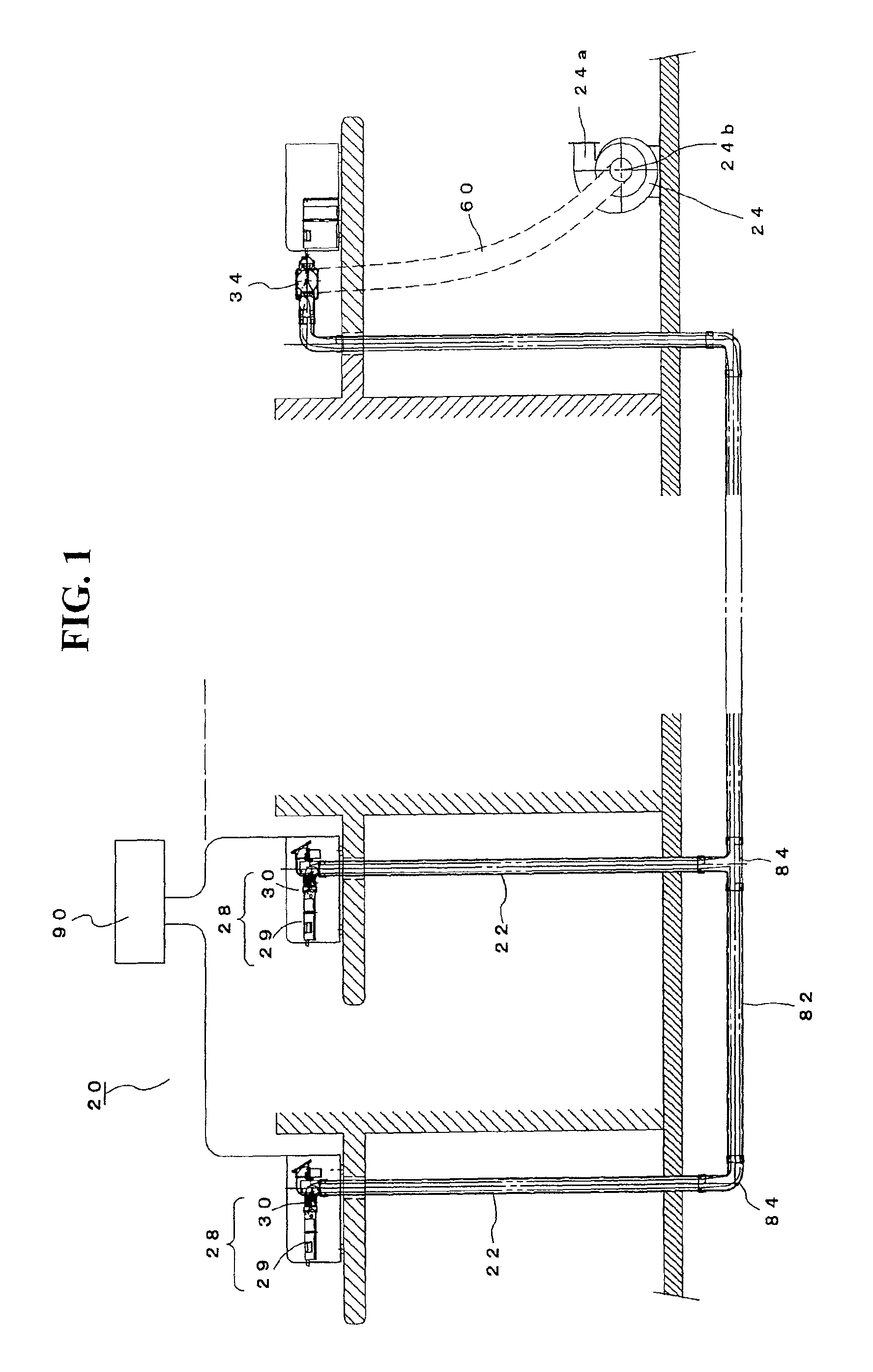
[0054]FIG. 1 is a schematic view of an entire equipment 20 for conveying sheet-shaped members.

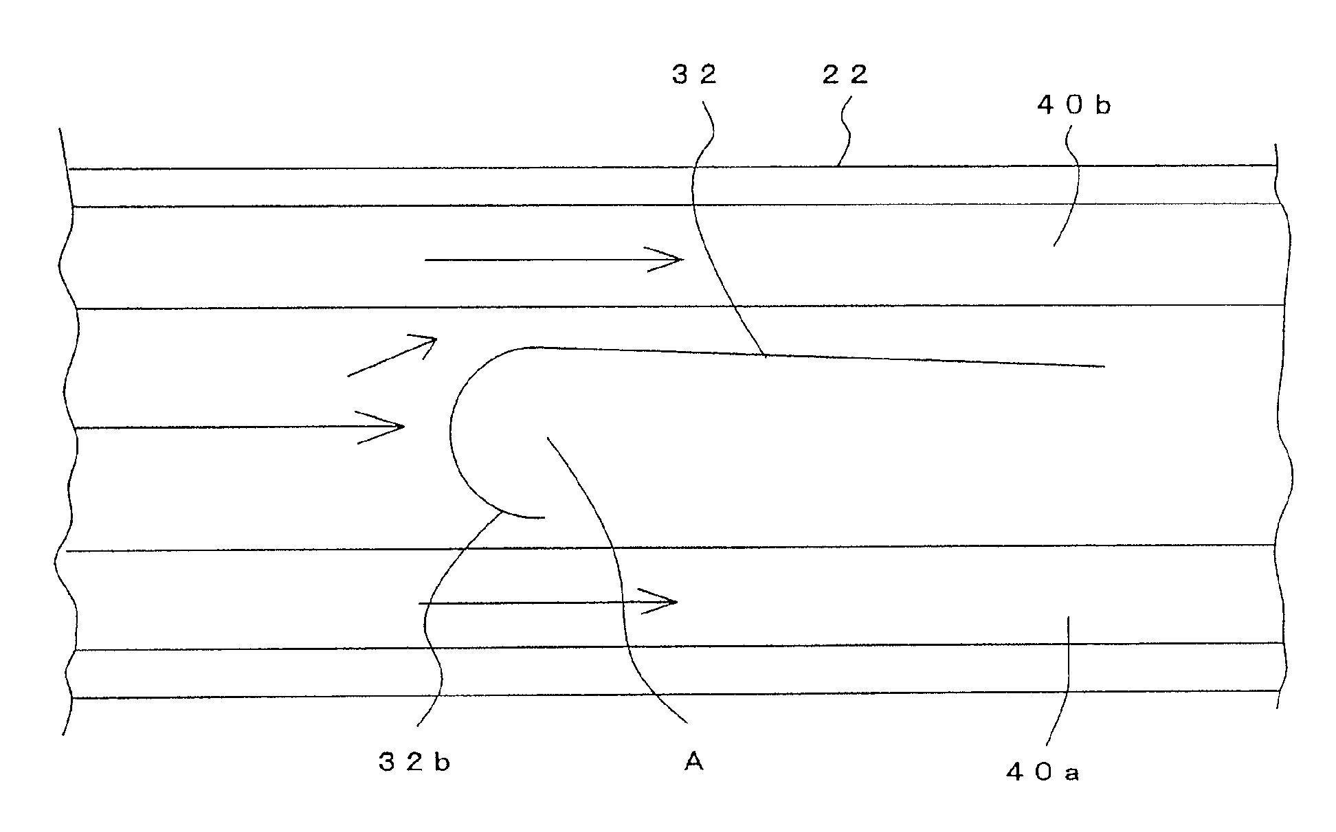
[0055]In FIG. 1, a plurality of blower ducts 22 (two ducts are shown in FIG. 1) are arranged parallel.

[0056]An outlet of each blower duct 22 is connected to a common duct 82 by a joint duct 84.

[0057]A flow passage area of the common duct 82 is substantially equal to that of each of the blower ducts 22. Note that, in the specification, the word “substantially equal” means that the flow passage area of the common duct is about 0.5-1.5 times as wide as that of the blower duct 22.

[0058]A symbol 24 stands for an air stream unit, which is constituted by a suction blower and which sucks air in the common duct 82 so as to generate air streams in the blower ducts 22. The air stream unit 24 sucks the air in the common duct 82 via a discharge pipe 60 connected to a collecting ...


PUM


Abstract

An equipment for conveying sheet-shaped members, including a plurality of blower ducts being arranged in parallel; a common duct connected to outlets of the blower ducts; an air stream unit for generating air streams in the blower ducts; a plurality of sheet feeding units respectively connected to the blower ducts, the sheet feeding units feeding sheet-shaped members into the blower ducts; a plurality of open/close valves respectively provided to the blower ducts, the open/close valves opening and closing the blower ducts; a drive section for respectively driving the open/close valves; a collecting unit provided to a terminal end of the common duct, the collecting unit collecting the sheet-shaped members conveyed; and a control section for controlling the drive section.

Description

CROSS-REFERENCE TO RELATED APPLICATION[0001]The present application is a National Stage application of International Application No. PCT / JP 2007 / 065342 filed on Aug. 6, 2007, and claims priority under 35 U.S.C. §119 to Japanese Patent Application No. 2006-228283 filed Aug. 24, 2006, the entire contents of which are hereby incorporated by reference.FIELD OF TECHNOLOGY[0002]The present invention relates to a method of conveying a sheet-shaped member by using an air stream and an equipment for conveying the sheet-shaped member.BACKGROUND TECHNOLOGY[0003]Banknote conveying equipments, each of which automatically conveys banknotes to a cash box set in a separate room or a separate building or to a storing room, have been used so as not to store banknotes in cash registers set in a supermarket, a convenience store, a game hall, etc. (see Patent Documents 1 and 2).[0004]In the conventional equipments, banknotes are conveyed by a belt mechanism or rollers.[0005]Patent Document 1: Japanese P...

Claims


Application Information

Patent Timeline
IPC IPC(8): B65H29/70
CPCB65G51/02B65H5/228B65G2201/022B65H2701/1912
Inventor TERASHIMA, TOSHIKATSU
Owner MARS ENG
Why Eureka
Try Eureka