Collapsible steering column assembly

a technology of steering column and assembly, which is applied in the direction of steering column, steering parts, vehicle components, etc., can solve the problems of steering column assembly collapse and negatively affect the performance of energy absorption devices, and achieve the effect of minimizing minimizing any increase in sliding frictional for

Inactive Publication Date: 2010-09-21
GM GLOBAL TECH OPERATIONS LLC +1
View PDF9 Cites 10 Cited by
  • Summary
  • Abstract
  • Description
  • Claims
  • Application Information

AI Technical Summary

Benefits of technology

[0007]The subject invention provides a steering column assembly for a vehicle. The steering column assembly comprises an upper jacket. The upper jacket defines an interior and extends along a longitudinal axis. A lower jacket is partially disposed within the interior. The lower jacket extends along the longitudinal axis. The upper jacket is moveable along the longitudinal axis relative to the lower jacket. A bushing is disposed between the upper jacket and the lower jacket. The bushing includes a forward edge and a rearward edge spaced from the forward edge along the longitudinal axis. A roller mechanism is coupled to the upper jacket. The roller mechanism includes a roller continuously engaging the lower jacket in rolling engagement. The roller is disposed adjacent one of the forward edge and the rearward edge of the bushing. The roller resists a resultant force transmitted between the upper jacket and the lower jacket in response to a load applied to the upper jacket transverse to the longitudinal axis. The roller minimizes an increase in sliding friction between the bushing and the lower jacket in response to the resultant force.
[0008]Accordingly, the roller mechanism reacts against the resultant force occurring between the upper jacket and the lower jacket as a result of the bending moment created by the transverse load applied to the upper jacket. The roller minimizes any increase in the sliding frictional force between the bushing and the lower jacket caused by the resultant force so that an energy absorption device may function properly.

Problems solved by technology

Such impacts during vehicle collision typically cause the steering column assemblies to collapse.
The increased frictional sliding force negatively affects the performance of the energy absorption device.

Method used


Image

  • Collapsible steering column assembly
  • Collapsible steering column assembly
  • Collapsible steering column assembly

Examples


Embodiment Construction

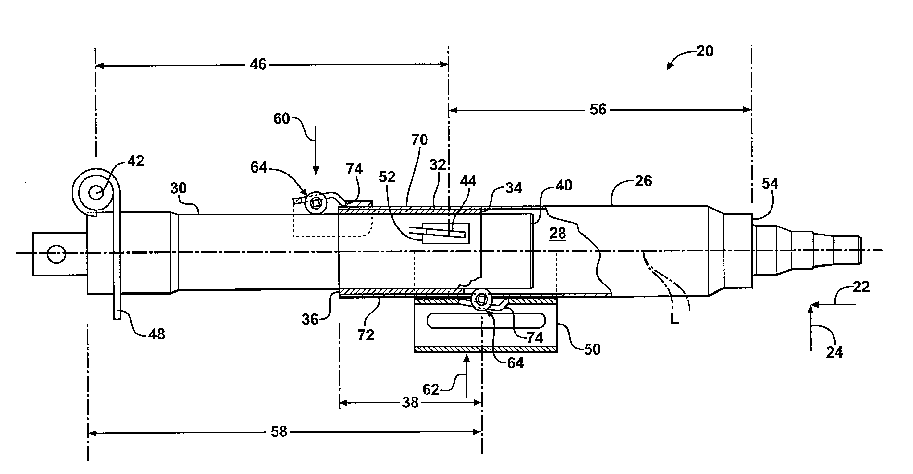
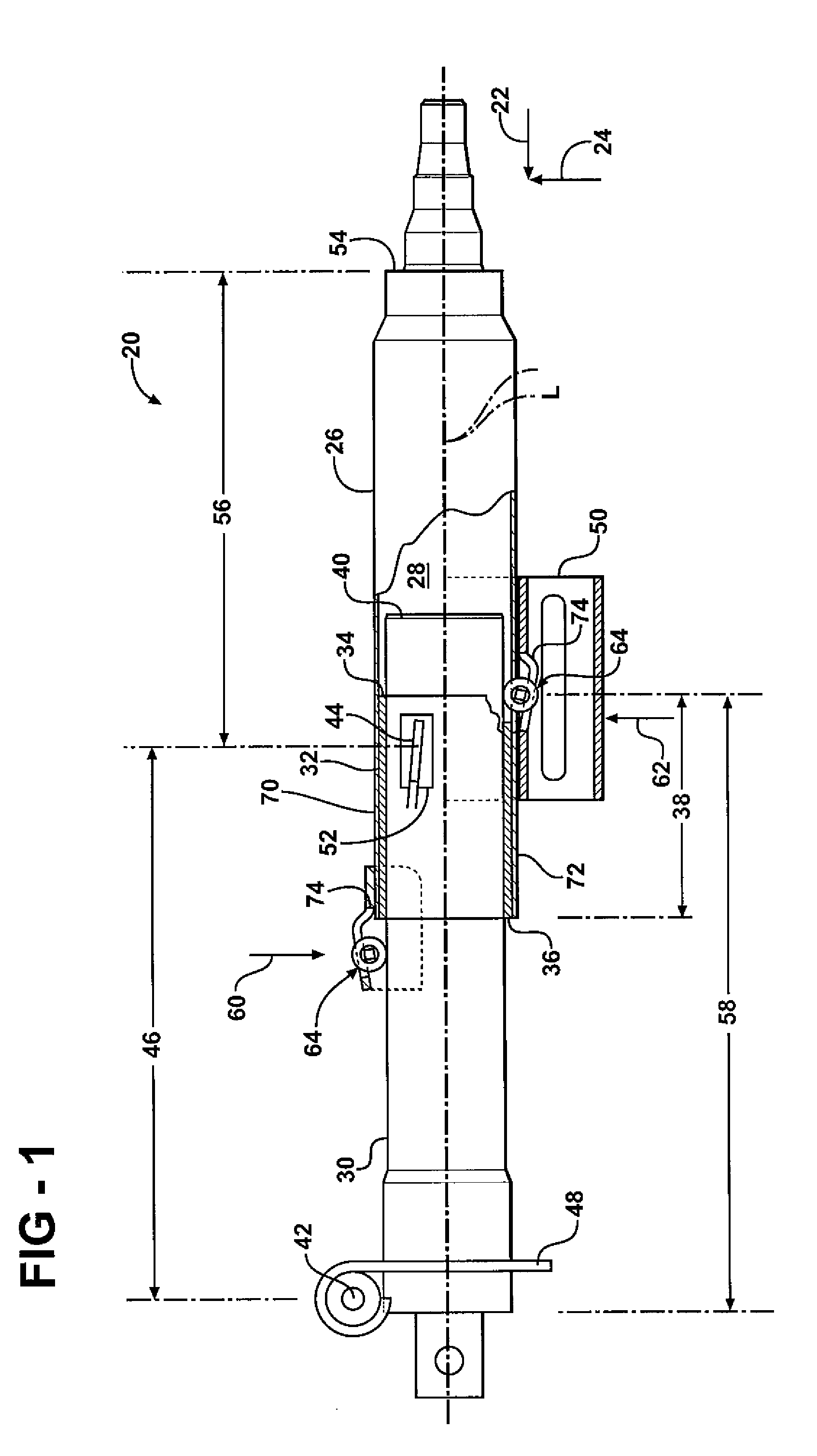
[0015]Referring to the Figures, wherein like numerals indicate corresponding parts throughout the several views, a steering column assembly is shown generally at 20. The steering column assembly 20 is for a vehicle and rotatably supports a steering wheel (not shown) as is well known. Referring to FIG. 1, the steering column assembly 20 is collapsible along a longitudinal axis L in response to a driver impacting the steering wheel during a collision event. The impact of the driver against the steering wheel transmits a load, i.e., a force, to the steering column to initiate the collapse stroke. The load applied to the steering column assembly 20 includes a longitudinal component 22 FL along the longitudinal axis L and a vertical component 24 transverse to the longitudinal axis L. The steering column assembly 20 includes an energy absorption device (not shown) for resisting the collapse stroke as is well known.

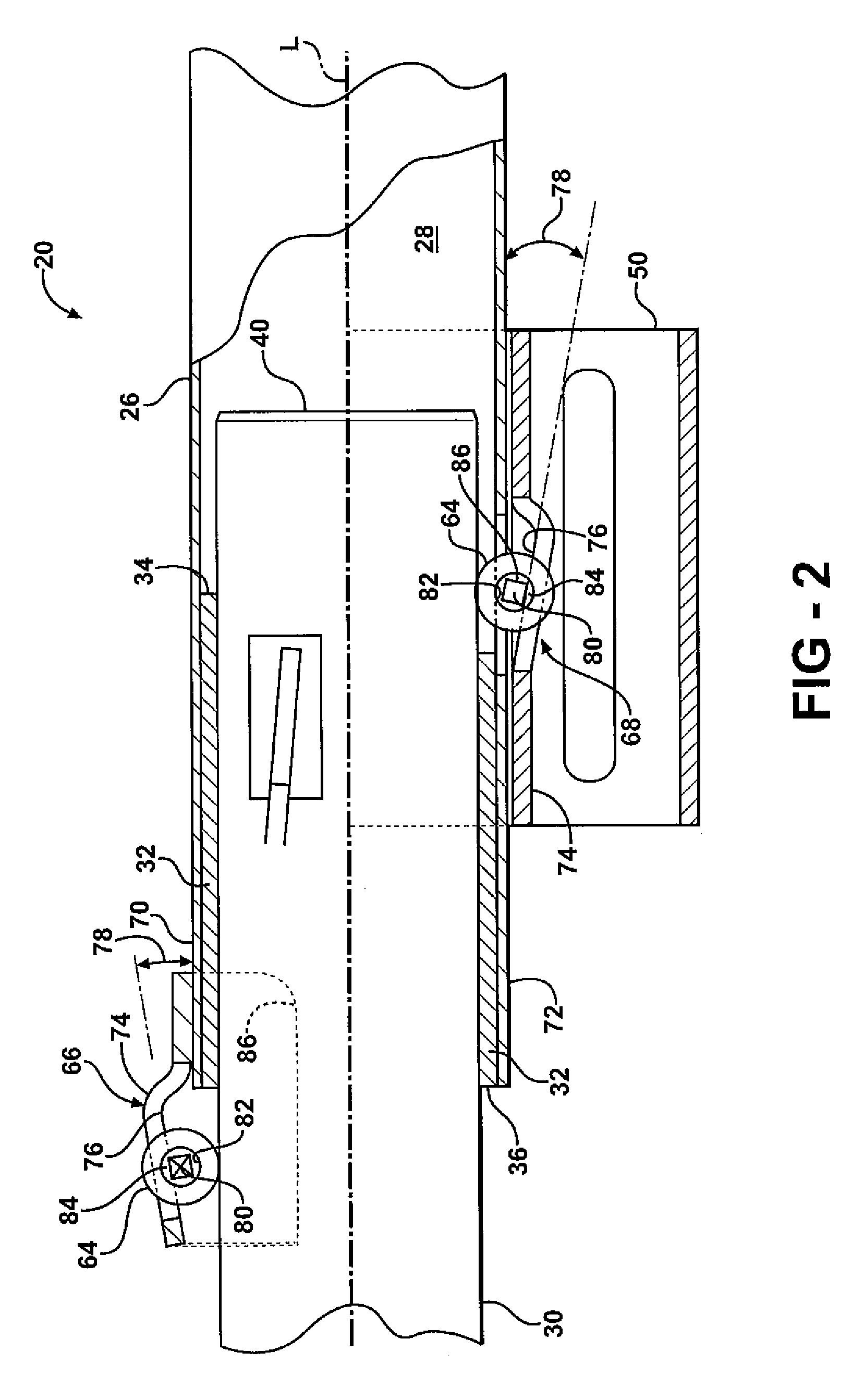
[0016]Referring to FIG. 2, the steering column assembly 20 comprises an upp...


PUM


Abstract

A steering column assembly includes an upper jacket and a lower jacket partially disposed within said upper jacket. A bushing is disposed between the upper jacket and the lower jacket. The upper jacket and the lower jacket are collapsible along a longitudinal axis in response to a collision event. A first roller mechanism and a second roller mechanism are mounted to the upper jacket near a forward end and a rearward end of the bushing respectively for engaging the lower jacket in rolling engagement. The first and second roller mechanisms resist a resultant force caused by a bending moment created by a transverse load applied to a distal end of the upper jacket to minimize an increase in a sliding frictional force between the bushing and the lower jacket.

Description

BACKGROUND OF THE INVENTION[0001]1. Field of the Invention[0002]The subject invention relates generally to a steering column assembly for a vehicle, and more specifically to a steering column assembly collapsible along a longitudinal axis in response to a collision event.[0003]2. Description of the Prior Art[0004]Automotive steering column assemblies are typically equipped with kinetic energy absorption devices. The energy absorption devices reduce injury to a vehicle operator caused by the operator impacting a steering wheel as a result of a collision event. Such impacts during vehicle collision typically cause the steering column assemblies to collapse. The energy absorption devices absorb the energy transmitted through the steering column assembly as the steering column assembly collapses.[0005]Such energy absorbing steering columns generally include a lower jacket disposed within an upper jacket. A bushing is disposed between the upper jacket and the lower jacket to de-lash the ...

Claims


Application Information

Patent Timeline
Patent Type & Authority Patents(United States)
IPC IPC(8): B62D1/19
CPCB62D1/192
Inventor CYMBAL, WILLIAM D.TINNIN, MELVIN L.RIEFE, RICHARD K.
Owner GM GLOBAL TECH OPERATIONS LLC
Why Eureka
Try Eureka