Electrosurgical instrument

a surgical instrument and electro-optical technology, applied in the field of electro-optical instruments, can solve the problems of difficult access into the slits, high cost implications, and difficult cleaning, and achieve the effects of increasing tissue tension, high corrosion resistance, and high wear resistance to mechanical stress

Active Publication Date: 2010-09-21
ERBE ELEKTROMEDIZIN GMBH
View PDF12 Cites 103 Cited by
  • Summary
  • Abstract
  • Description
  • Claims
  • Application Information

AI Technical Summary

Benefits of technology

[0014]The basis of the invention is that the guide gap expands in the direction which faces away from a cutting area between the electrode parts on both electrode parts. Precise guidance of the cutting instrument is thus possible in direct proximity to the cutting area based on the tapered construction of the guide gap. The coagulation zone of the electrode parts is hardly disrupted. The other areas of the guide gap are at the same time easily accessible and thus easy to clean. If the guide gap has to be re-worked, for example a coating having to be applied, then this can be carried out easily because of the improved access.
[0036]In a further preferred embodiment the insulating section is formed as the particular or each surface profile supporting the particular or each tensioning effect. A short circuit is thus prevented from occurring between the electrode parts in the simplest way as well as the tensioning of the tissue being increased.

Problems solved by technology

With this embodiment of the slits their preparation for reuse, that is to say cleaning, is very time-consuming as the access into the slits is made difficult.
This has considerable cost implications.

Method used


Image

  • Electrosurgical instrument
  • Electrosurgical instrument
  • Electrosurgical instrument

Examples


Embodiment Construction

[0045]The same reference numerals will be used in the following description for the same parts and parts with the same function.

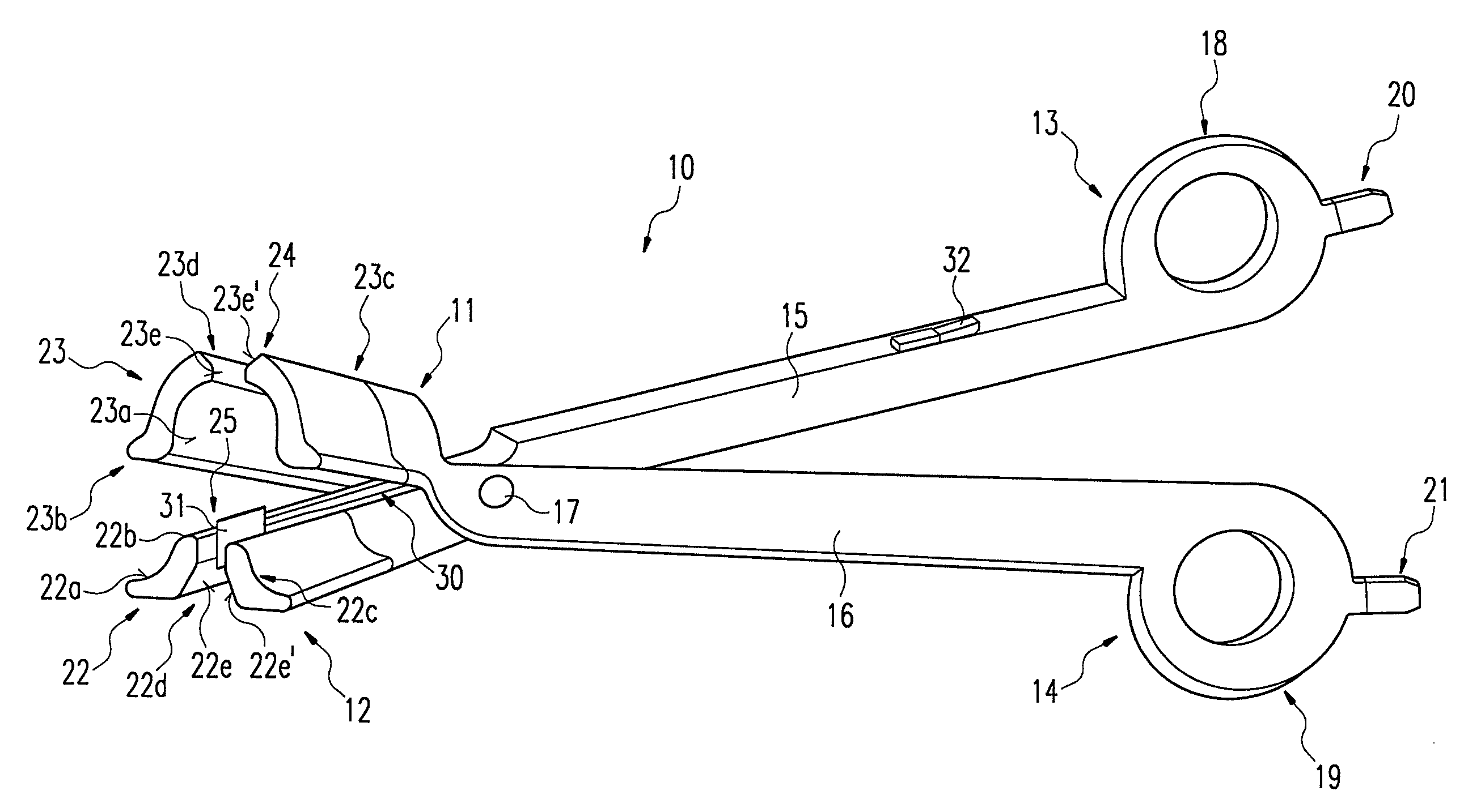
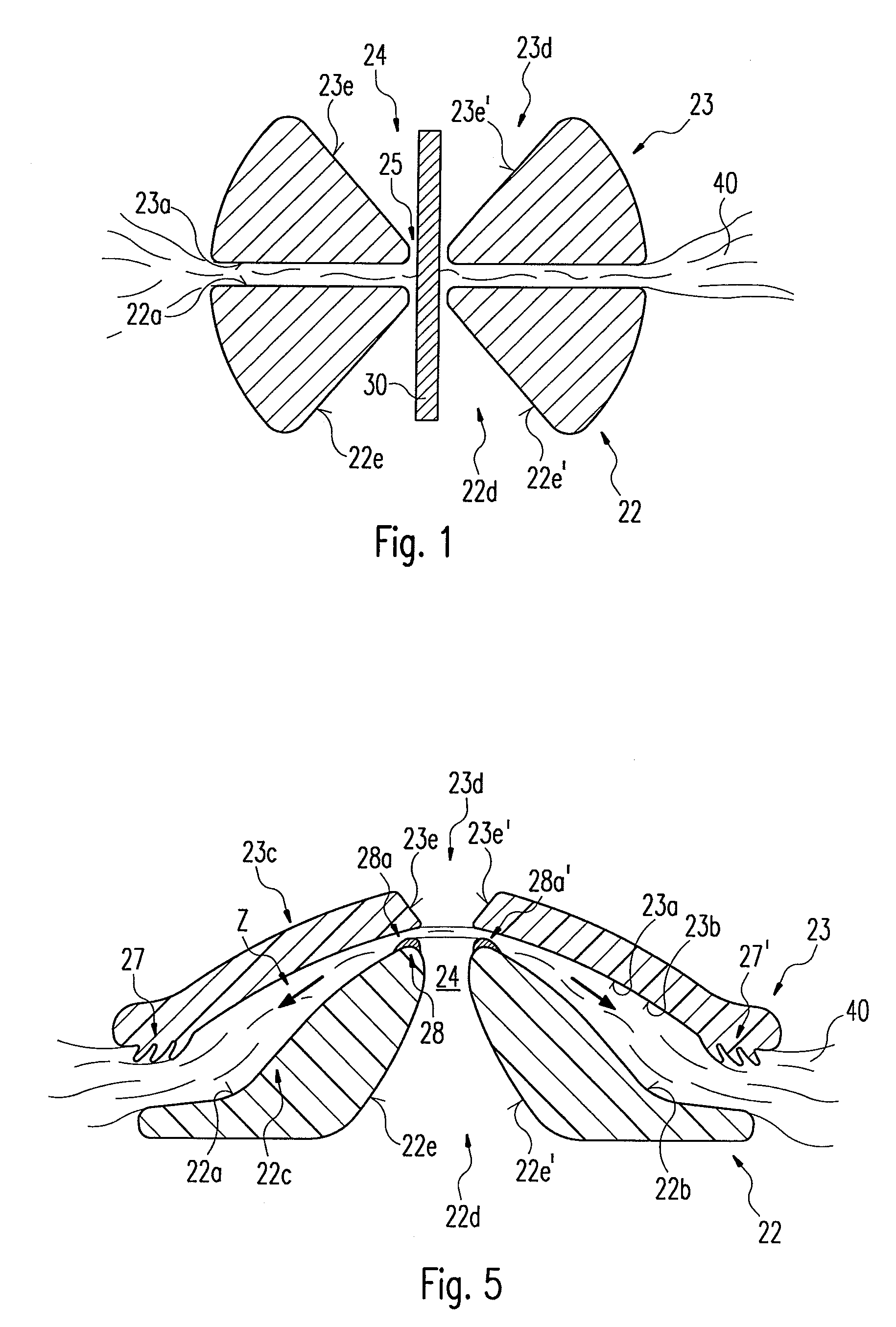
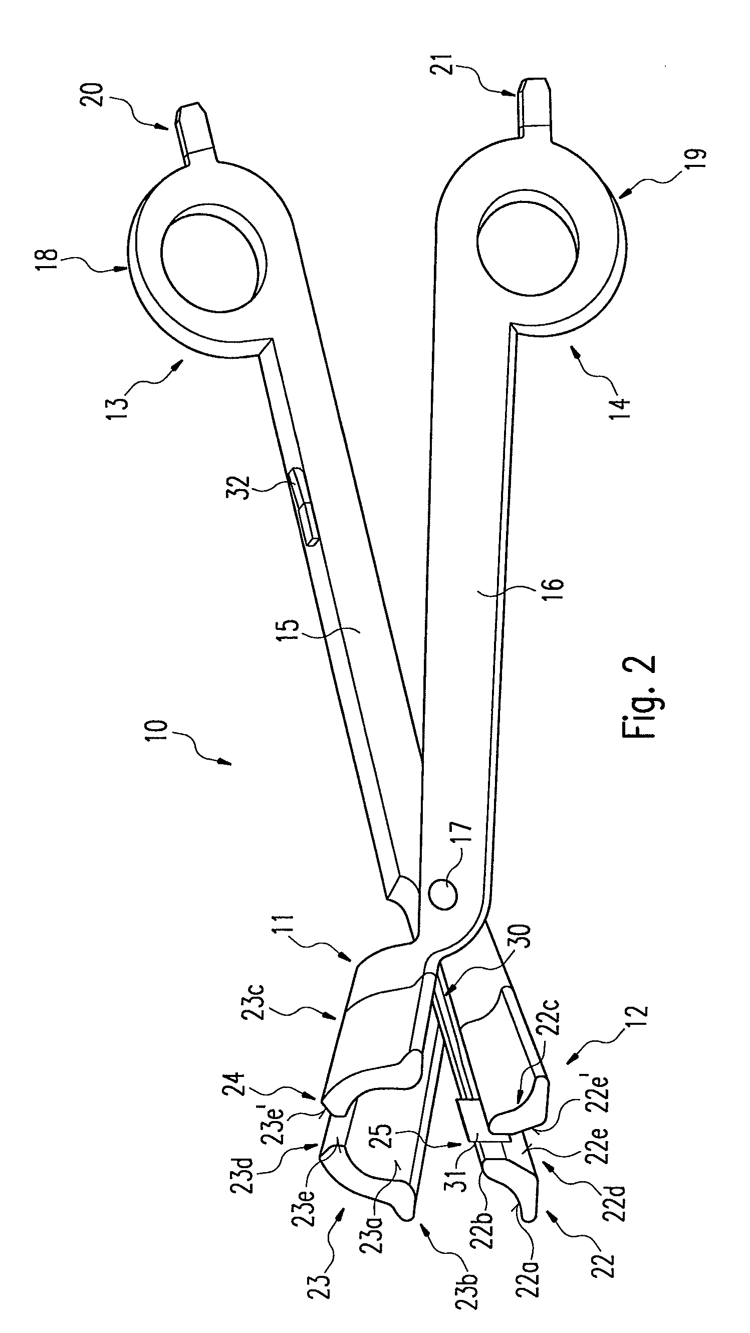
[0046]FIG. 1 shows a schematic front view section of the enlarged electrode layout according to a first preferred embodiment. The electrode layout is, for example, provided on an electrosurgical instrument, as described in more detail in FIG. 2. The electrode parts 22, 23 comprise open regions 22d, 23d which form a guide gap 24 for a cutting instrument 30. Due to the open regions 22d, 23d the electrode parts 22, 23 comprise two respective areas. The cutting instrument 30 can therefore be placed on the clamped tissue 40 for carrying out a cutting procedure. The guide gap 24 also facilitates a precise cut of the tissue 40, because the cutting instrument 30 can be guided along the guide gap 24. This is advantageous when the cutting instrument 30 is operated mechanically. As can be seen from the diagram the open regions 22d, 23d are aligned so as not to impede ...


PUM


Abstract

The invention relates to an electrosurgical instrument comprising two limbs that have an articulated connection and that can be actuated in the manner of a cutting or a clamping tool. The instrument also comprises opposing electrode parts with coagulation surfaces on distal ends of its limbs for holding a vessel or tissue and for passing a current through said vessel or tissue to cause it to coagulate. At least one electrode part has an open region that acts as a guide gap for a cutting instrument, so that the electrode part(s) is / are divided into at least two areas and the cutting instrument can be applied to the clamped vessel or tissue to execute a cutting operation. In addition, current supply devices supply the coagulation current from a high-frequency generator to the electrode parts. The improved configuration of said electrosurgical instrument allows the open region on the electrode part(s) to afford optimal guidance of a cutting instrument, whereby said open region can be easily prepared for additional cutting operations and / or be subjected to an after-treatment. To achieve this, the two or more open regions of the electrode part(s) comprise respective opposing separation surfaces that taper in the direction of the coagulation surfaces.

Description

RELATED U.S. APPLICATIONS[0001]Not applicable.STATEMENT REGARDING FEDERALLY SPONSORED RESEARCH OR DEVELOPMENT[0002]Not applicable.REFERENCE TO MICROFICHE APPENDIX[0003]Not applicable.FIELD OF THE INVENTION[0004]The invention relates to an electrosurgical instrument comprising two limbs that have an articulated connection and that can be actuated in the manner of a cutting or clamping tool.BACKGROUND OF THE INVENTION[0005]Electrosurgical instruments have been used for many years in high-frequency surgery especially in order to coagulate biological tissue as well as to cut it. For coagulation a high-frequency current is passed through the tissue to be treated, so that it changes due to protein coagulation and dehydration. The tissue contracts in such a way that the vessels are closed and bleeding is staunched. After coagulation has taken effect the tissue can, for example, be separated by means of a mechanically operating cutting instrument.[0006]Electrosurgical procedures can be carr...

Claims


Application Information

Patent Timeline
Patent Type & Authority Patents(United States)
IPC IPC(8): A61B18/18A61B18/14
CPCA61B18/1442A61B2018/1412A61B2018/1455
Inventor HAFNER, DIETER
Owner ERBE ELEKTROMEDIZIN GMBH
Why Eureka
Try Eureka