
Modularized prosthesis leg cover

a technology of prosthesis and leg covers, applied in the field of prosthesis legs, can solve the problems of difficult cutting, disadvantages of conventional soft and one-piece prosthesis leg covers made of urethane foam, and increase production costs, so as to reduce the number of parts, easy production, and the effect of increasing productivity

Inactive Publication Date: 2010-09-21
MATSUMOTO P&O +1
View PDF11 Cites 11 Cited by
  • Summary
  • Abstract
  • Description
  • Claims
  • Application Information

AI Technical Summary

Benefits of technology

[0008]The modularized prosthesis leg cover of the present invention is advantageous compared to conventional prosthesis leg covers made of foam for the following reasons. 1) The modularized prosthesis leg cover can be easily produced. 2) The modularized prosthesis leg cover can quickly cover a prosthesis leg after quickly assembling prefabricated modules with each other to form the prosthesis leg cover. 3) The modularized prosthesis leg cover can cover a prosthesis leg without being limited by the shapes or kinds of parts of the prosthesis leg, so that the modularized prosthesis leg cover has wide applicability. 4) The modularized prosthesis leg cover can avoid damage, degradation, deformation or breakage, thus having high durability. 5) The appearance of the modularized prosthesis leg cover is similar to the appearance of a real leg. Particularly, when the knee joint part is bent, the appearance of the modularized prosthesis leg cover is natural. 6) The modularized prosthesis leg cover is light, thus having high practical utility. 7) The modularized prosthesis leg cover does not affect bending motion of the knee joint part, which is an important skeletal part of the prosthesis leg.
[0019]According to the ninth aspect of the present invention, there is provided a method for manufacturing a modularized prosthesis leg cover, comprising; designing a plurality of modules, which are obtained by grouping parts of the prosthesis leg cover into a plurality of groups, each comprising a plurality of associated parts, and producing the modules; and assembling the produced modules with each other, thus forming a prosthesis leg cover. When the prosthesis leg cover is designed and produced as a modularized system, as described above, modules that fit a patient can be easily manufactured. Further, a desired prosthesis leg cover, which fits a patient, can be quickly provided by selecting suitable modules from among prefabricated modules and assembling the selected modules with each other to form a prosthesis leg cover. In other words, a variety of prosthesis leg covers, which fit different patients and thus have different shapes and sizes, can be efficiently and quickly provided.

Problems solved by technology

The conventional soft and one-piece prosthesis leg covers made of urethane foam are disadvantageous as follows.
1) The kneecap is repeatedly expanded and contracted, thus becoming damaged within a short period of time.
2) The conventional soft and one-piece prosthesis leg covers do not have a symmetrical cylindrical shape, so that it is very difficult to cut them.
Particularly, while a patient, wearing the conventional prosthesis leg cover, swings his / her prosthesis leg, the prosthesis leg cover hinders the functionality of the knee joint part.
Thus, the conventional foam covers for covering the prosthesis legs take a long time to produce and are thus very expensive.

Method used


Image

  • Modularized prosthesis leg cover
  • Modularized prosthesis leg cover
  • Modularized prosthesis leg cover

Examples


first embodiment

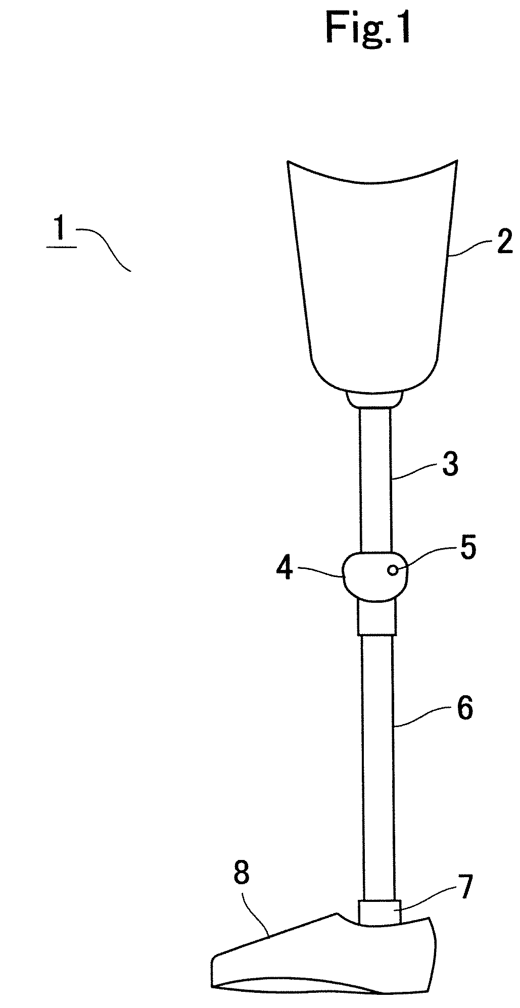
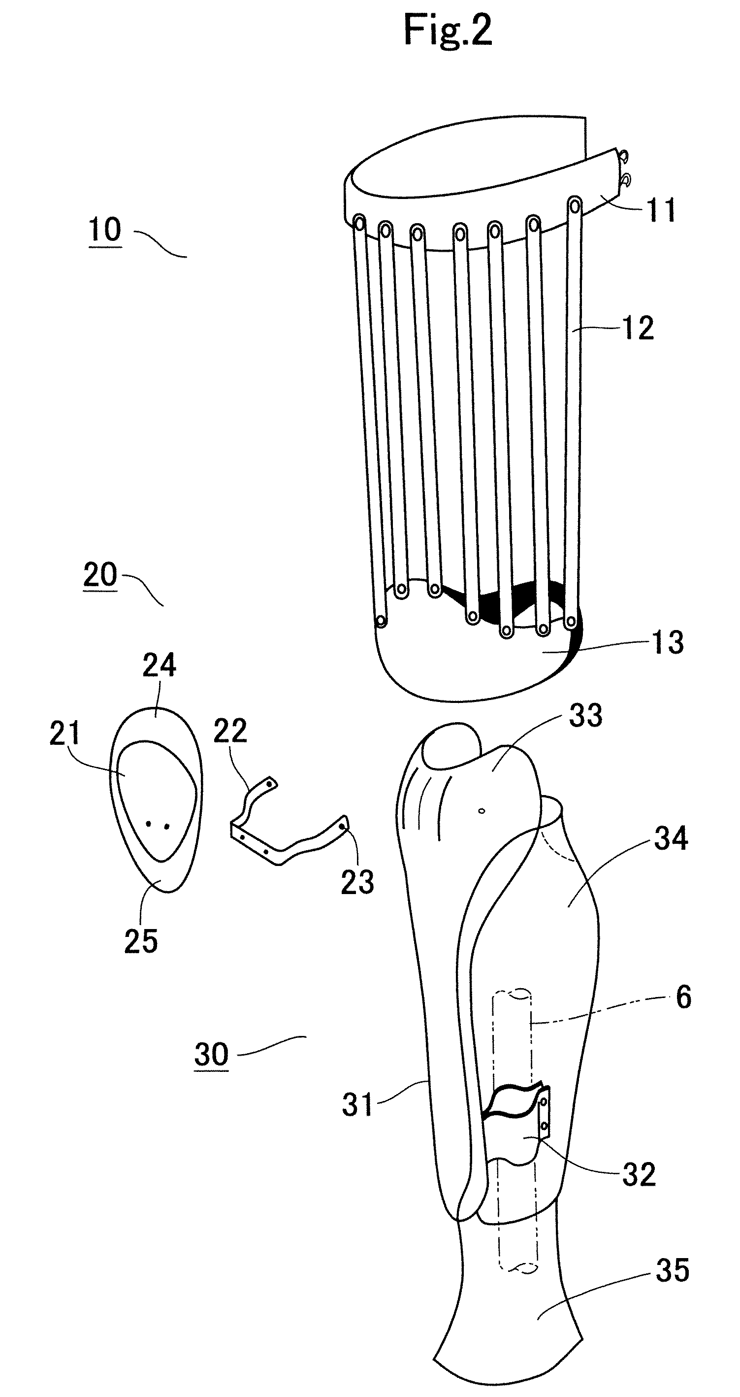
[0041]FIG. 2 is an exploded perspective view illustrating parts of the modularized prosthesis leg cover according to the present invention. As shown in the drawing, the prosthesis leg cover comprises: a thigh module 10, which is mounted to the thigh socket 2 and surrounds the thigh 2; a patella module 20, and a lower leg module 30, which is mounted to the lower leg pipe 6 and surrounds the lower leg pipe 6. The thigh module 10 comprises: a proximal annular band 11, which surrounds the proximal part of the thigh of the patient; a plurality of longitudinal strips 12 mounted to the proximal annular band 11; and a distal annular band 13, which is mounted to the distal ends of the longitudinal strips 12. Thus, the thigh module 20 has a basket appearance. The proximal annular band 11 is preferably attached to the thigh socket 2 of the prosthesis leg 1 using a Velcro fastener. The plurality of longitudinal strips 12 and the distal annular band 13 are preferably made of a plastic material, ...

second embodiment

[0048]FIG. 5 is an exploded perspective view illustrating a skin module according to the present invention, which functions as a support, instead of the stay, for supporting a patella part. In this embodiment, the skin module 53 covers both a thigh shell 51 and a lower leg shell 52. The skin module 53 comprises contractible tights made of a stretchable fiber. FIG. 5 shows that the skin module 53 is folded down at the kneecap. The skin module 53 is provided with an inside pocket 54, which has a lid flap and is provided on the rear portion of the skin module 53 at a position diametrically opposite the knee joint part. The inside pocket 54 receives a patella part 55 therein. The patella part 55 comprises: a hard resin layer 55A, which is made of a hard synthetic resin and forms a rear layer of the patella part 55; a soft middle layer 55B, which is made of soft urethane foam; and a leather layer 55C, which forms an outside layer of the patella part 55. When the patella part 55 is config...

third embodiment

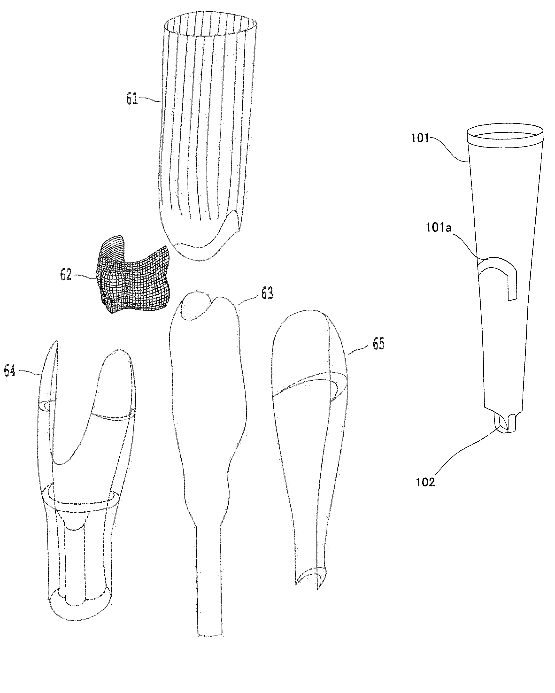
[0051]FIG. 7 is a rearview illustrating the prosthesis leg cover of the present invention. In FIG. 7, the lower leg front pad 64 and the lower leg rear pad 65 are not shown. When the thigh module 61, the patella module 62 and the lower leg module 63 are assembled with each other to form a prosthesis leg cover, two protrusions 62a, which are formed on opposite sides of the rear part of the patella module 62, are inserted into respective grooves 67 and 68, which are provided between a lower round surface 61a of the thigh module 61 and an upper round surface 63a of the lower leg module 63 and are formed from the front part to the opposite sides of the knee joint part. Due to the engagement of the two protrusions 62a with the respective grooves 67 and 68, the location of the patella module 62 can be more reliably set. Thus, the patella module 62 can execute a motion similar to that of a real leg.


PUM


Abstract

A modularized prosthesis leg cover quickly covers a prosthesis leg and does not affect bending or stretching motion of a knee joint part of the prosthesis leg, thus preventing damage to the knee joint part of the prosthesis leg. Thus, the modularized prosthesis leg cover includes a thigh module, which can be mounted to a thigh socket of the prosthesis leg, a lower leg module, which can be fastened to a calf pipe of the prosthesis leg, and a patella module, which can be rotatably assembled with the lower leg module. The prosthesis leg cover, which is formed by assembling the modules, is covered with a skin module, which is made of a stretchable fiber. The respective modules are provided as prefabricated modules. A method of manufacturing the prosthesis leg cover is also provided.

Description

BACKGROUND OF THE INVENTION[0001]1. Field of the Invention[0002]The present invention relates, in general, to prosthesis legs and, more particularly, to a cover for endoskeletal prosthesis legs.[0003]2. Description of the Related Art[0004]Generally, endoskeletal prosthesis legs have been preferably used because they having many functional advantages. In conventional endoskeletal prosthesis legs, the skeletons of the prosthesis legs are important functional parts, so that a shell or a cover for covering a prosthesis leg is required. In the related art, to provide a shell or a cover for covering the endoskeletal prosthesis leg, a cylindrical urethane foam block is cut to form the thigh part or the calf part of a lower leg part. Of course, the thigh parts or the calf parts of conventional prosthesis leg covers must be specifically produced as integral one-piece parts to fit patients. The conventional soft and one-piece prosthesis leg covers made of urethane foam are disadvantageous as ...

Claims


Application Information

Patent Timeline
Patent Type & Authority Patents(United States)
IPC IPC(8): A61F2/74
CPCA61F2/60A61F2/64A61F2002/5001A61F2002/5053A61F2002/5083A61F2002/607A61F2002/608A61F2002/648A61F2002/7862A61F2002/7881
Inventor TAKAMI, KENJIAOYAMA, TAKASHIHAYASHI, MITSURUMIYAGAWA, TAKUYAAKUTAGAWA, MASAYASUZUKI, MITSUHISA
Owner MATSUMOTO P&O
Learn More