Wind energy installation and method of controlling the output power from a wind energy installation

a technology of wind energy installation and output power, which is applied in the direction of electric generator control, machine/engine, dynamo-electric converter control, etc., can solve the problems of increasing output power loss, counter-weighting loss, and only losing output power outside the dead band, so as to improve the reaction to grid frequency changes

Active Publication Date: 2010-09-21
SIEMENS GAMESA RENEWABLE ENERGY AS
View PDF22 Cites 14 Cited by
  • Summary
  • Abstract
  • Description
  • Claims
  • Application Information

AI Technical Summary

Benefits of technology

[0008]It is an objective of the present invention to provide a method of controlling the out-put power from a wind energy installation and a wind energy installation which allow an improved reaction to changes of the grid frequency.

Problems solved by technology

In these state of the art methods, output power is only lost outside the dead band.
Although the inventive method slightly increases the output power loss due to the reduced dead band and, in particular, due to not having a dead band at all, this loss is counter-weighted by the increased ability to quickly react to deviations of the actual grid frequency from the nominal grid frequency.

Method used


Image

  • Wind energy installation and method of controlling the output power from a wind energy installation
  • Wind energy installation and method of controlling the output power from a wind energy installation
  • Wind energy installation and method of controlling the output power from a wind energy installation

Examples


first embodiment

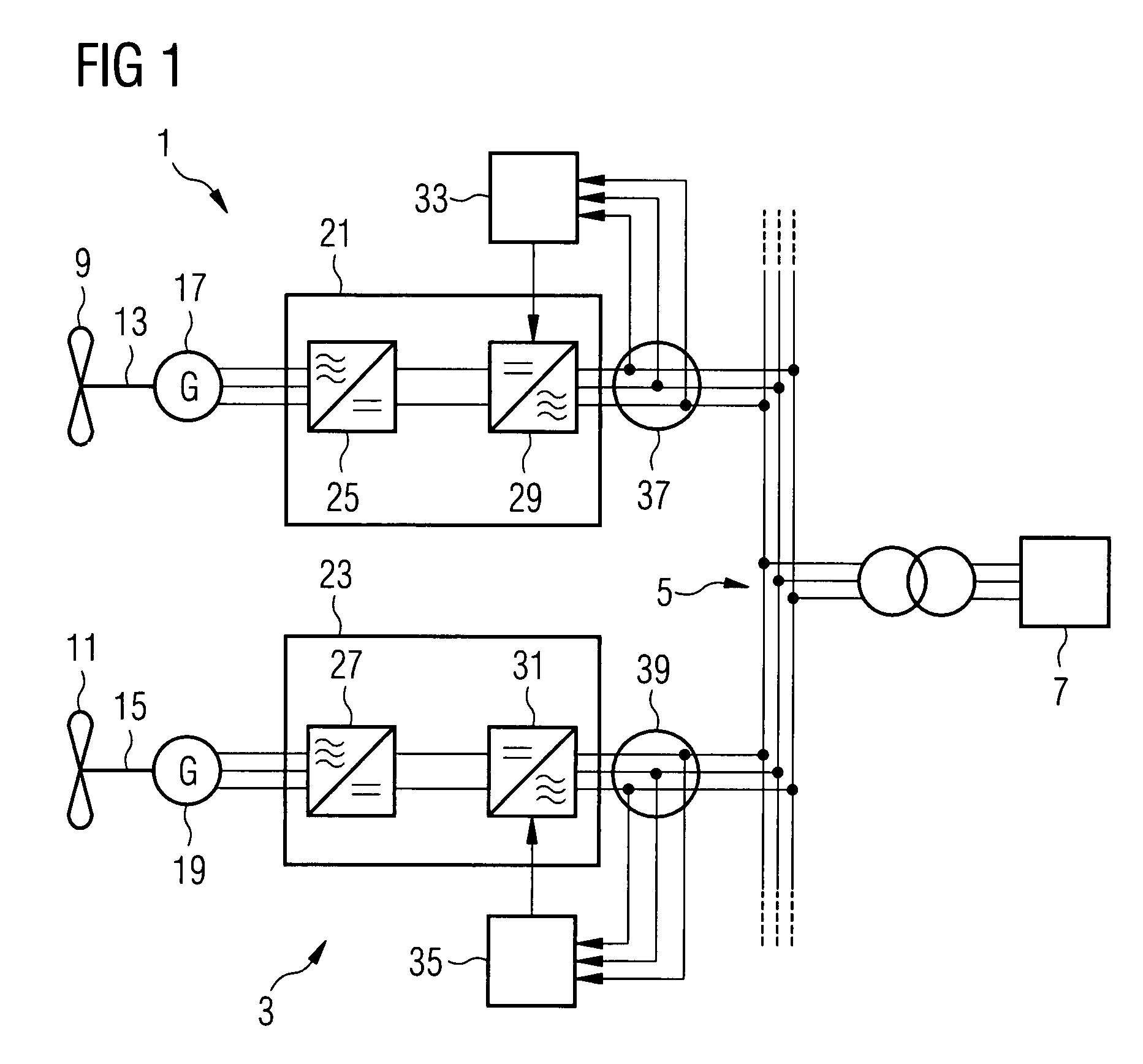
[0023]The wind energy installation shown in FIG. 1 comprises a number of wind turbines two of which are exemplary shown in the figure. The wind turbines 1, 3 produce electrical output power and are connected via an internal node 5 to an external utility grid 7. Although the first embodiment comprises more than one wind turbine, it can also be implemented for a single wind turbine.

[0024]The wind turbines 1, 3 are variable speed wind turbines, i.e., the rotational speed of the rotor 9, 11 is allowed to vary depending on the wind conditions.

[0025]Each wind turbine 1, 3 comprises a rotor 9, 11 with a shaft 13, 15 transmitting the torque of the wind driven turning rotor 9, 11 to an AC generator 17, 19 which transforms the mechanical power provided by the rotation of the shaft 13, 15 into electrical power. Although not shown in the Figure, the shaft 13, 15 may be divided into a rotor shaft extending from the rotor to an optional gearbox and an output shaft extending from the gearbox to th...

second embodiment

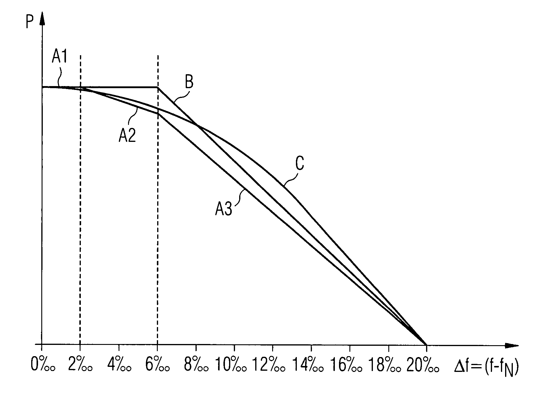
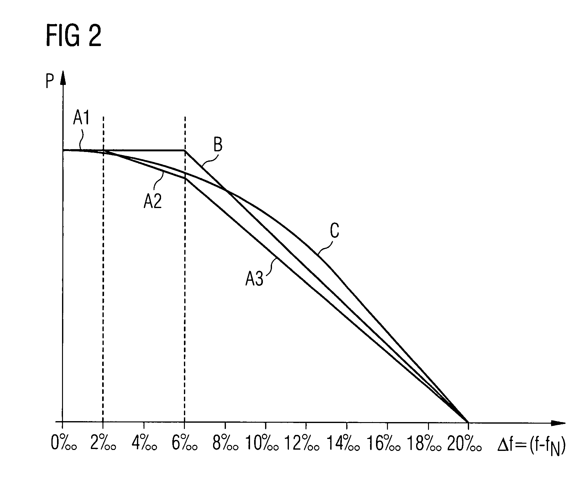
[0034]In the invention the output power P is reduced according to a non-linear function of the grid frequency deviation Δf In the present embodiment, this function is chosen such that the output power P becomes zero as soon as the frequency deviation Δf reaches 20 per mill. The output power P is reduced as soon as the measured grid frequency f exceeds the nominal grid frequency and is, e.g. a negative quadratic or cubic function of the frequency deviation Δf. Note that although the output power is a negative quadratic or cubic function of the frequency deviation in the present embodiment, the output power could be any non-linear function reducing the output power with increasing frequency deviation Δf, in particular, any negative polynomial. Furthermore, a non-linear function could, e.g., be represented by a transfer function. Another possibility would be to combine linear and non-linear functions, e.g. defining a linear function for a first frequency range and a non-linear function...


PUM


Abstract

A method of controlling the output power from a wind energy installation to a utility grid having a specified nominal frequency is provided, in which the output power is controlled depending on the actual grid frequency in the utility grid such that the output power is reduced when the grid frequency exceeds a predetermined value. The predetermined value is at most two per mill higher than the nominal frequency of the grid and the output power is reduced as soon as any increase of the grid frequency above the predetermined value is detected.

Description

CROSS REFERENCE TO RELATED APPLICATIONS[0001]This application claims the benefits of European application No. 06021973.0 filed Oct. 19, 2006, and is incorporated by reference herein in its entirety.FIELD OF INVENTION[0002]The present invention relates to a wind energy installation, i.e. a single wind turbine or a wind farm comprising a number of wind turbines. The invention further relates to a method of controlling the output power from such a wind energy installation to an electrical grid for which a nominal grid frequency is specified.BACKGROUND OF THE INVENTION[0003]Many wind energy installations are not stand alone installations provided for a single user but feed the generated electrical power into a grid which distributes the power to a large number of different users. As the power consuming devices of the users require electrical power within a certain parameter range, e.g., a specified nominal voltage and a specified nominal grid frequency, measures are necessary to ensure ...

Claims


Application Information

Patent Timeline
Patent Type & Authority Patents(United States)
IPC IPC(8): F03D9/00H02P9/04F02D29/06
CPCF03D7/0272F03D7/0284F03D9/003H02J3/38F05B2270/337Y02E10/723Y02E10/763F03D15/20F03D9/255Y02E10/72Y02E10/76
Inventor STIESDAL, HENRIK
Owner SIEMENS GAMESA RENEWABLE ENERGY AS
Why Eureka
Try Eureka