
Head immobilisation assembly for patient positioning in radiation therapy

a patient positioning and immobilisation assembly technology, applied in the direction of patient positioning for diagnostics, therapy, application, etc., can solve the problems of affecting the positioning affecting the patient's face along the contact surface area, and the fitting of the template may become too tight, so as to achieve the effect of precise repositioning of the patient's head

Active Publication Date: 2010-09-28
ORFIT IND
View PDF12 Cites 8 Cited by
  • Summary
  • Abstract
  • Description
  • Claims
  • Application Information

AI Technical Summary

Benefits of technology

"The present invention provides an immobilization assembly for a patient that provides optimal positioning, fixation, and comfort to the patient. The assembly includes a template that exerts a pull force on the body part to be treated, along the contact surface area, to restrain its displacement. The fixation force is adjusted to the body part to ensure stability and precision during treatment. The assembly also includes means for adjusting the fixation force to compensate for any changes in the size of the body part. This ensures that the patient is always comfortable and improves the stability and precision of the immobilization device."

Problems solved by technology

However, depending on the nature of the thermoplastic material used, the fitting of the template may become too tight when the thermoplastic material has fully cooled down, or it may become or too loose after a while with shrinking dimensions of the body part.
When applied to the patients' head and face after having been moulded a few days ago, as a result of the additional shrinking occurred during annealing, often the template fits too tightly to the face, thus rendering the contact between the inner surface of the template and for example the patients' face along the contact surface area uncomfortable.

Method used


Image

  • Head immobilisation assembly for patient positioning in radiation therapy
  • Head immobilisation assembly for patient positioning in radiation therapy
  • Head immobilisation assembly for patient positioning in radiation therapy

Examples


Embodiment Construction

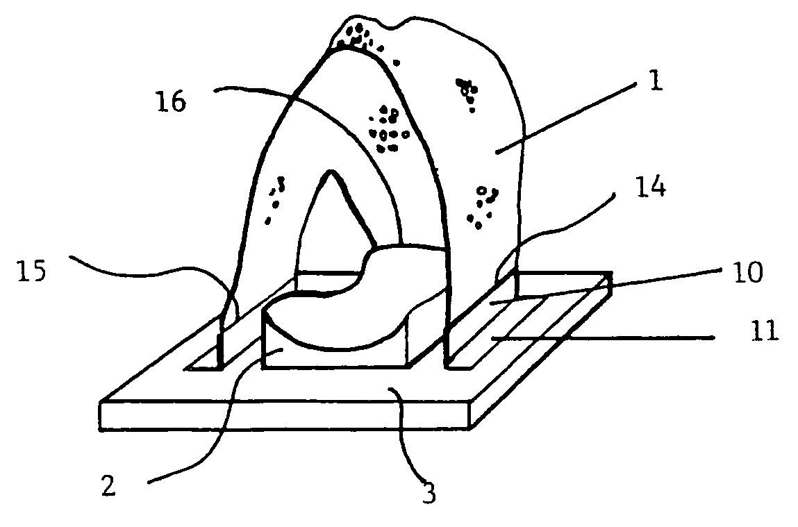
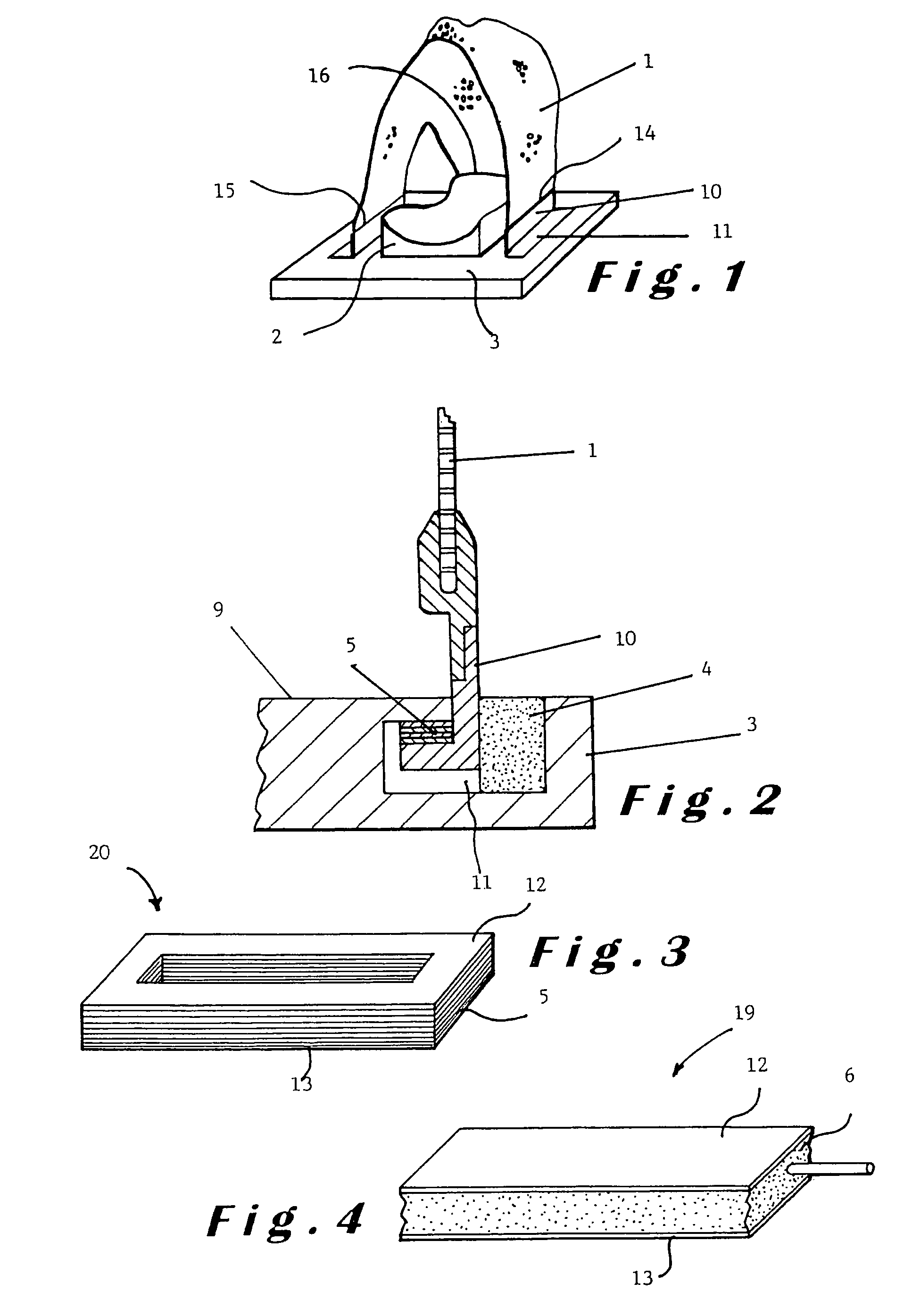
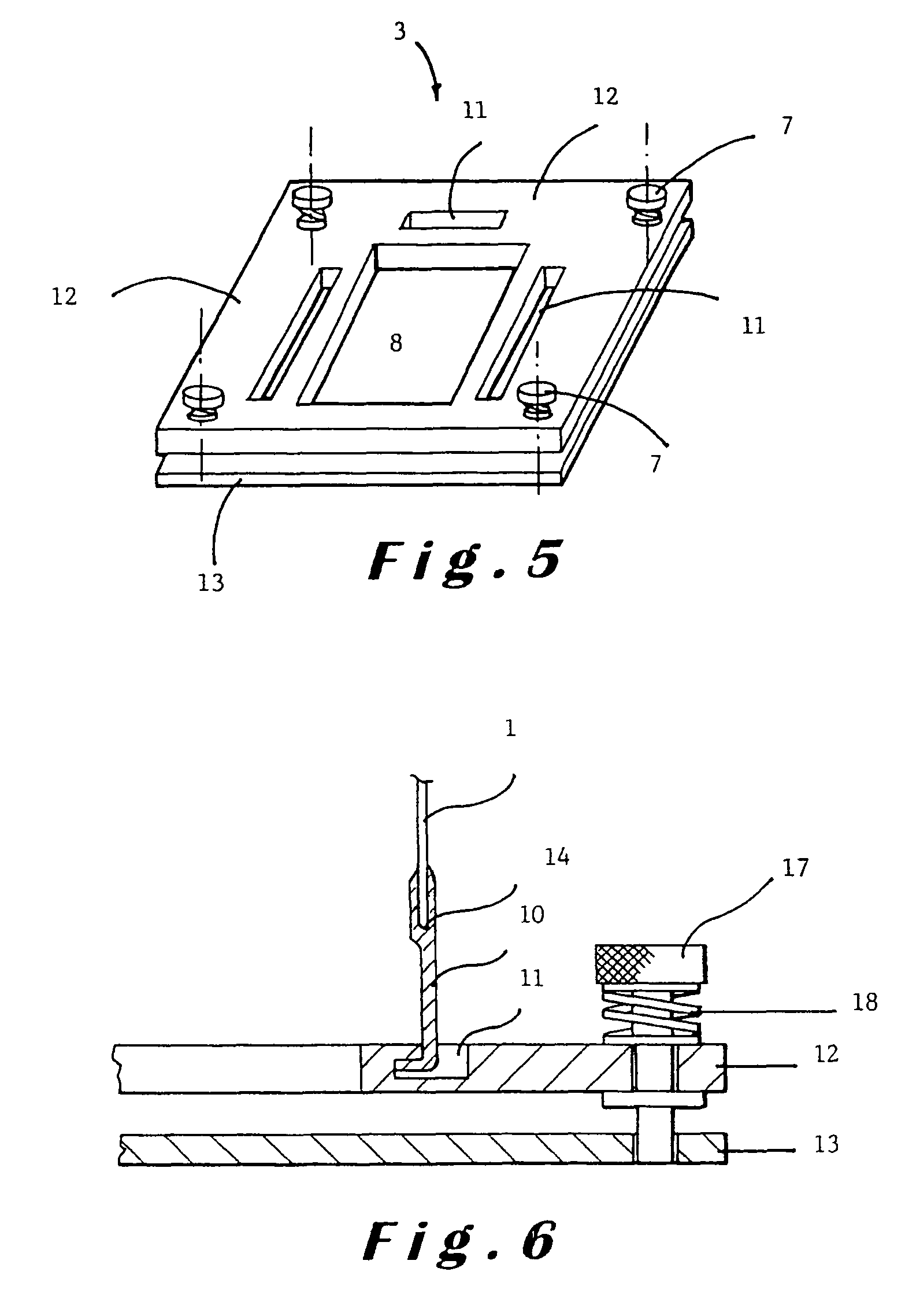
[0030]The embodiment of the assembly of this invention shown in FIG. 1 comprises a template 1, the position of which is fixed by connecting it to a fixation plate 3. In the embodiment shown, the template 1 is provided to cover at least part of the head of a patient. Thereby the inner surface of the template contacts at least part of the surface of the body part that needs to be immobilized and defines the contact surface area between the two. However, the template may be designed to cover the entire face or head or to partially or fully cover any other body part of a human being or an animal.

[0031]The template 1 shown in FIG. 1 is preferably made of a thermoplastic material, which is moulded by positioning the patients' head onto the fixation plate. If so desired, to improve comfort to the patient and to improve the patient positioning and reproducibility thereof, the head and neck may be supported by a head and neck support 2.

[0032]For the sake of simplicity and because of the part...


PUM


Abstract

This invention relates to a non-invasive patient immobilisation assembly for immobilising a body part of a patient and for at least temporarily fixing the position thereof. The immobilisation assembly comprises a rigid template (1) made of a thermoplastic material. The template is thermoformed or otherwise moulded in such a way that the inner surface conforms to and contacts the body part to be immobilised along a contact surface area between the template and the body part. The contact surface area corresponds to at least part of the inner surface of the template. The immobilisation assembly also comprises a fixation plate (3, 12, 13) and connecting means (10, 11, 14, 15, 16) for connecting the template (1) to the fixation plate (3, 12, 13) in view of fixing the position of the template and the body part with respect to the fixation plate. The template (1) is provided to exert a fixation force of a preset value to the body part covered by it along the contact surface area by exerting a pulling force pulling the body part towards the fixation plate (3, 12, 13) with the aim of restraining the displacement of the body part within the template within defined limits. The assembly further comprises means (5, 6, 7, 17, 18) for adjusting the fixation force exerted by the template to the preset value.

Description

CROSS REFERENCE TO RELATED APPLICATION[0001]This application is a continuation-in-part of U.S. application Ser. No. 10 / 581,596, filed Jun. 5, 2006.FIELD AND BACKGROUND OF THE INVENTION[0002]The present invention relates to a non-invasive patient immobilisation assembly for immobilising a body part of a patient and for at least temporarily fixing the position thereof, wherein the immobilisation assembly comprises a rigid template made of a thermoplastic material, which template is thermoformed or otherwise moulded in such a way that the inner surface conforms to and contacts the body part to be immobilised along a contact surface area which corresponds to at least part of the inner surface of the template, wherein the immobilisation assembly also comprises a fixation plate and connecting means for connecting the template to the fixation plate in view of fixing the position of the template and the body part with respect to the fixation plate, as described in the preamble of the first ...

Claims


Application Information

Patent Timeline
Patent Type & Authority Patents(United States)
IPC IPC(8): A61F5/04A61F5/37A61B5/055A61B6/04A61B19/00A61N5/10
CPCA61B19/203A61F5/3707A61B6/0421A61B2019/206A61G13/121A61N5/1049A61N2005/1097A61B90/18A61B90/14
Inventor CUYPERS, STEVENBOGDANOV, BOGDAN
Owner ORFIT IND
Learn More