
Belt tensioning system for vertical conveyor belt

Active Publication Date: 2010-09-28
TRANSNORM SYST
View PDF17 Cites 4 Cited by
  • Summary
  • Abstract
  • Description
  • Claims
  • Application Information

AI Technical Summary

Benefits of technology

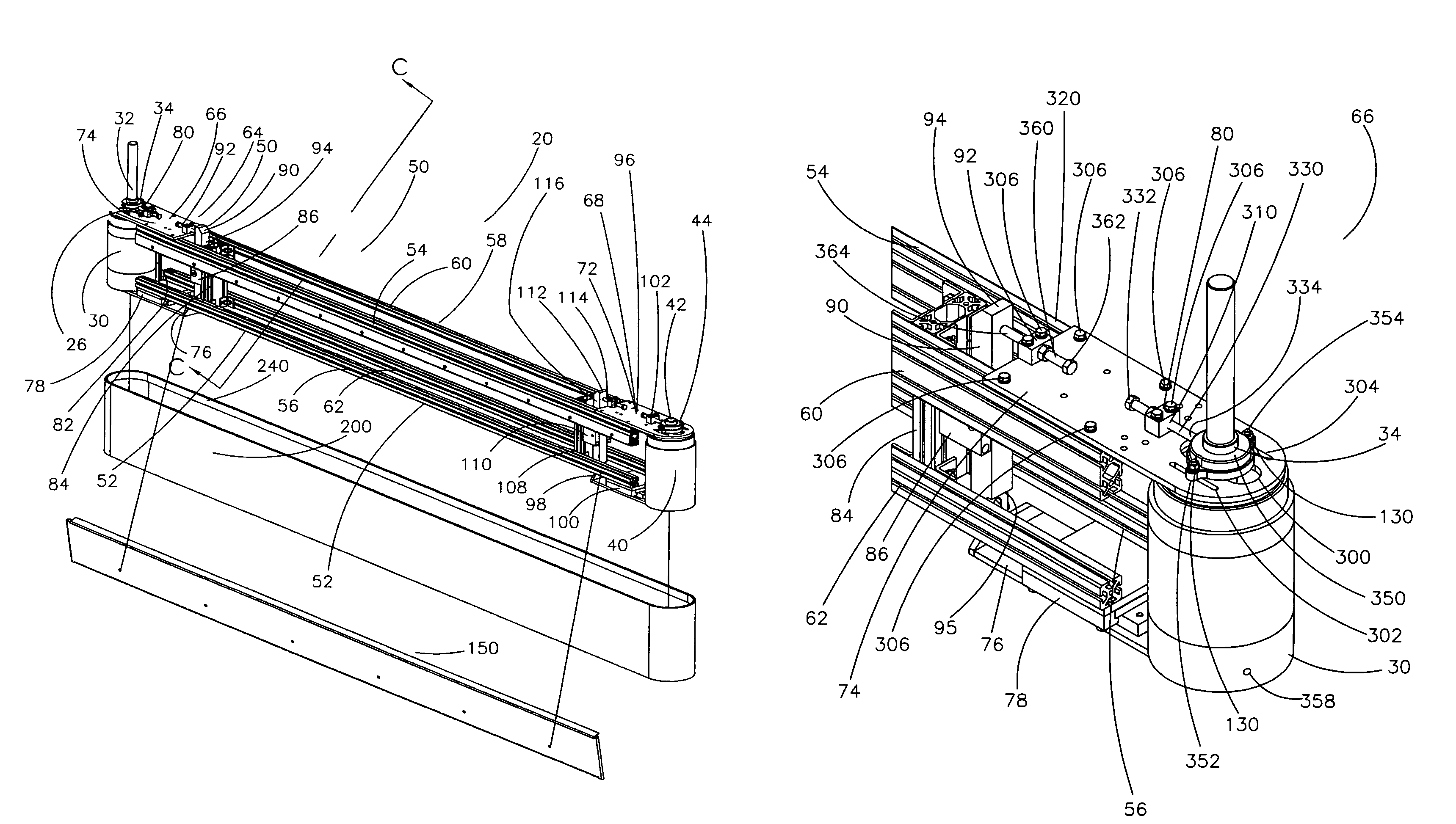
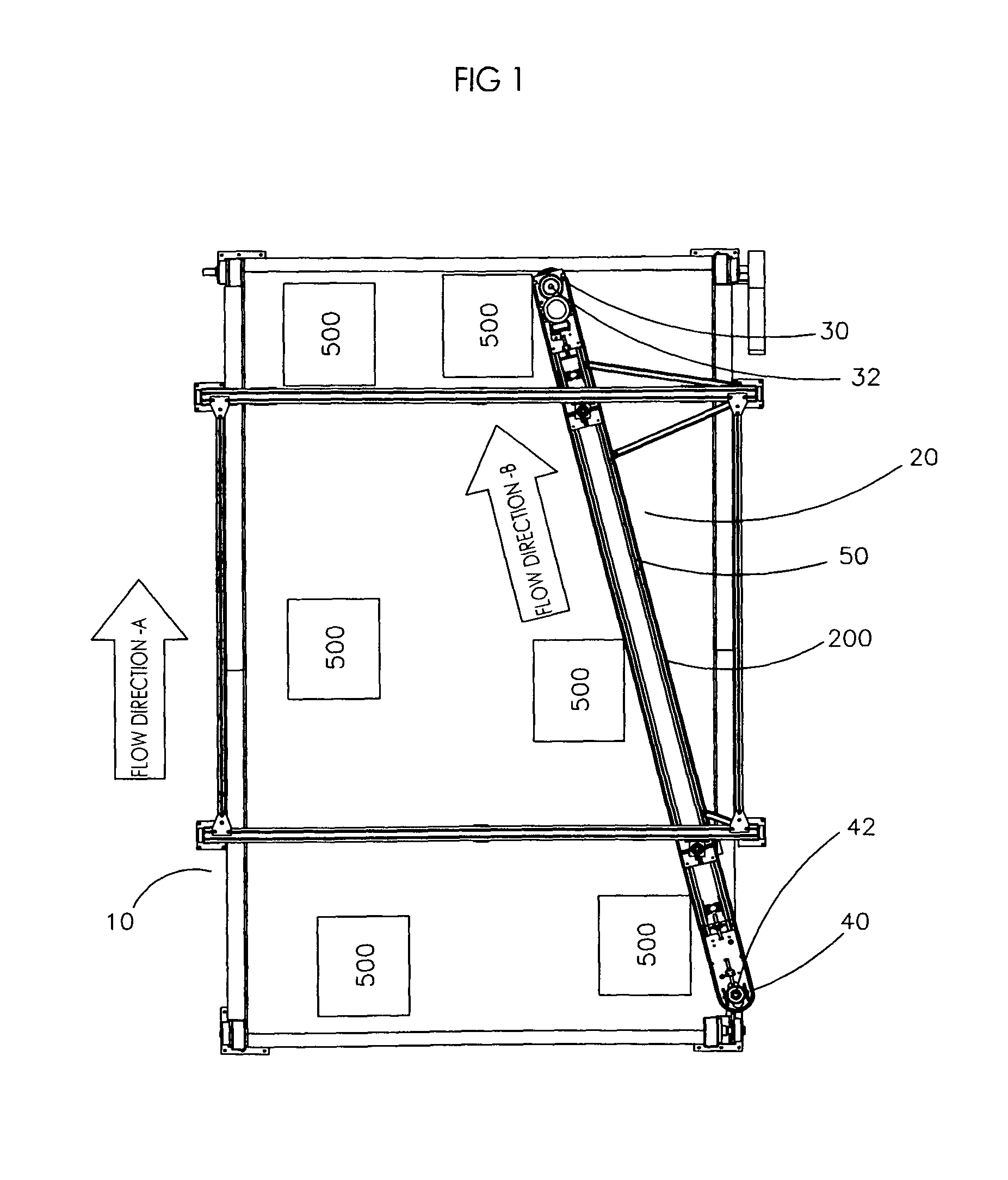
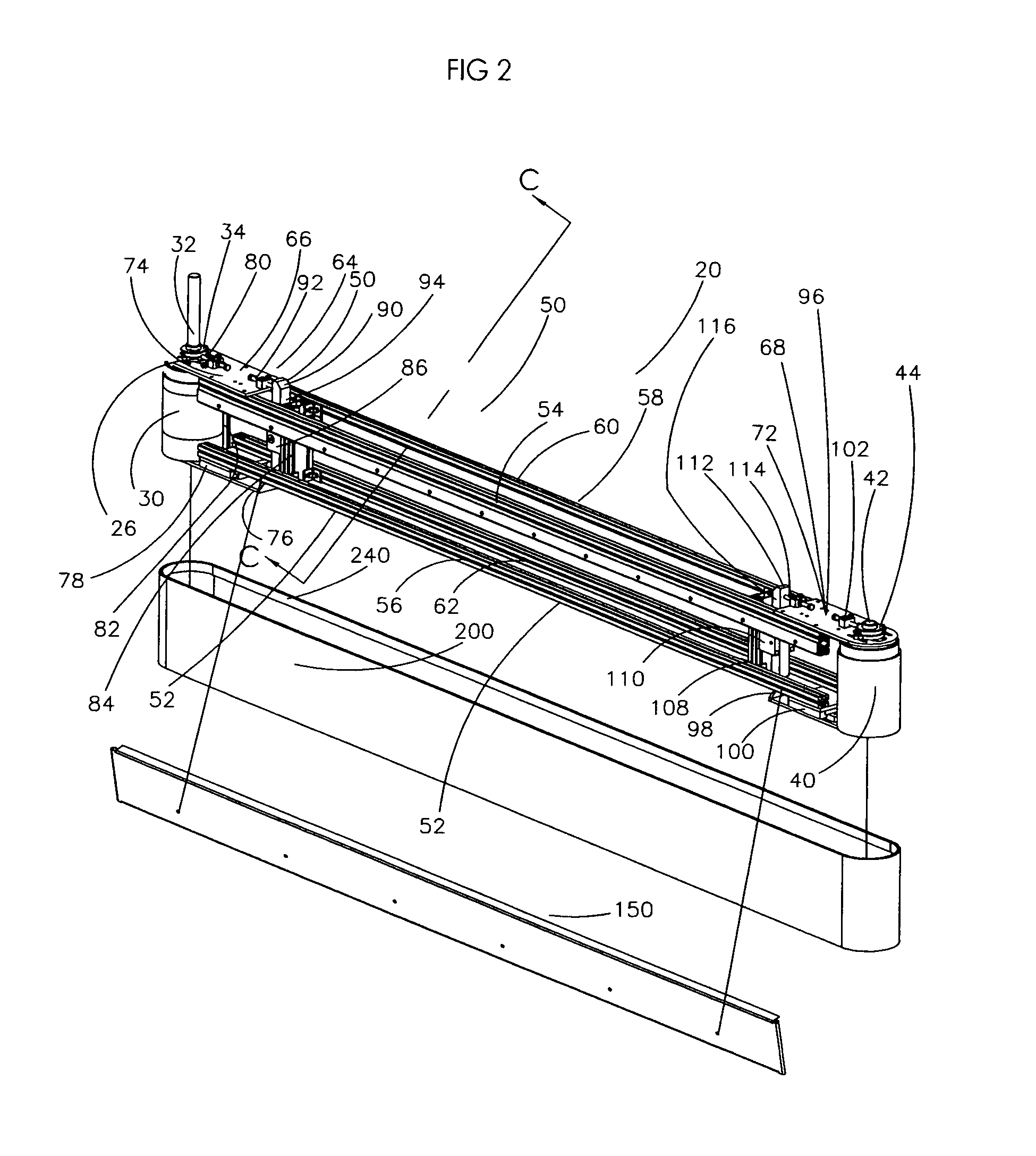
[0012]The present invention eliminates various problems attributable to previous vertical conveyor belt mounting systems while meeting the long felt but unfulfilled need of providing a simple system of applying tension to the vertical conveyor belt as the vertical conveyor belt traverses about the vertical conveyor or diverter assembly without the need of raising the vertical conveyor belt several centimeters above the horizontal conveyor or the need of using specialized tools to adjust the lower bearings associated with the drive pulley or follower roll.
[0025]Yet another embodiment of the present invention and method can be described as a method of applying force to a pulley or a follower roll supplying tension to a vertical conveyor belt, comprising the steps of: a) mounting an upper support plate, including a plurality of apertures, to a first belt support and a second belt support parallel to the first belt support; b) securing a slidable first rotable bearing about at least one of said plurality of apertures; c) securing a lower movable plate, having a second rotable bearing mounted thereon, about a first horizontal member and a second horizontal member parallel to the first horizontal member; d) mounting a lever between the first belt support, the second belt support, the first horizontal member and the second horizontal member; e) mounting a force stabilizer device to the upper support plate such that the force stablizer can contact a housing of the first rotable bearing; f) mounting a force application device to an opposite end of the upper support plate such that the force application device can contact the upper section of the lever; g) securing the pulley or follower roll to the first rotable bearing and the second rotable bearing; h) locking the first rotable bearing for preventing the first rotable bearing from sliding; i) using the force stabilizer to apply tension to said vertical conveyor belt; and j) causing the force application device to contact the upper section of the lever such that the lower section of the lever pivots to abut the lower movable plate causing the second rotable bearing to move the pulley or the follower roll against the vertical conveyor, thereby increasing the tension applied to the vertical conveyor belt.

Problems solved by technology

One of the difficulties associated with prior vertical conveyor belt mounts required that the bottom of the vertical conveyor belt be mounted several centimeters above its corresponding horizontal conveyor belt.

Method used


Image

  • Belt tensioning system for vertical conveyor belt
  • Belt tensioning system for vertical conveyor belt
  • Belt tensioning system for vertical conveyor belt

Examples


Embodiment Construction

[0041]Although the disclosure hereof is detailed to enable those skilled in the art to practice the invention, the embodiments published herein merely exemplify the present invention.

[0042]In the most general sense, the present invention is system for applying tension to a vertical conveyor belt. More specifically, the current belt tensioning system includes combination of a force application device, a force stabilization device and a pivoting lever to increase tension applied to the vertical conveyor belt. Within the scope of the present invention, the vertical conveyor belt contacts a pulley or follower roll that is connected between an upper rotable bearing and a lower rotable bearing. The rotable bearings are connected with or supported by either a stationary plate or a movable plate associated with the conveyor frame supporting the vertical belt.

[0043]The combination of the coupling members, a drive pulley and follower roll and a novel and nonobvious belt tensioning system allo...


PUM


Abstract

The present invention is a system for applying tension to vertical conveyor belts. A combination of force stabilizing devices, force adjusting devices, movable plates and pivoting levers allows adjustment of the tension applied to the vertical conveyor belt. The levered tensioning allows the vertical conveyor belt to positioned in closed proximity with another conveyor or object.

Description

BACKGROUND OF THE INVENTION[0001]A) Field of the Invention[0002]Among other things, the present invention is related to belt tensioning systems for vertical conveyor belts. A combination of force stabilizing devices, force adjusting devices, movable plates and pivoting levers allows adjustment of the tension applied to the vertical conveyor belt. The belt tensioning system provides levered tensioning of the vertical conveyor belt and allows the vertical conveyor belt to be positioned in close proximity with a horizontal conveyor or other apparatus.[0003]B) Description of the Previous Art[0004]1) U.S. Pat. No. 5,161,665—Cragun enables a lane merger apparatus. Column 5, lines 32-65, of the '665 Patent reads, “Referring to FIGS. 5 and 7, each side transfer conveyor 18 further has a support or backing structure 76 which enables the rotating belts 31 to engage and maintain engagement of the articles 21 in the central conveyance path. The support structure 76 is disposed directly behind t...

Claims


Application Information

Patent Timeline
IPC IPC(8): B65G23/44
CPCB65G23/44B65G47/766
Inventor MCGUIRE, PATRICK M.WIER, DONALD K.
Owner TRANSNORM SYST
Learn More