Enclosure for wiring devices

a wiring device and enclosure technology, applied in the direction of connection contact material, electrical apparatus casing/cabinet/drawer, coupling device connection, etc., can solve the problems of time-consuming and involved, and achieve the effect of avoiding the time of manually stripping, safety and quick mounting

Inactive Publication Date: 2010-09-28
ASLAN INDS
View PDF16 Cites 11 Cited by
  • Summary
  • Abstract
  • Description
  • Claims
  • Application Information

AI Technical Summary

Benefits of technology

[0009]The newly design wiring device enclosure of the present invention will eliminate the time of manually stripping away the insulated jacket and individual conductors by use of Q-CEB (Quick-Connect Electrical Box) connectors as described in Libby, U.S. Pat. Nos. 5,975,938 and 7,144,269B2 and 7,281,941. The wiring device, whether it be a receptacle outlet, a switch, a ground fault receptacle, a three or four way switch, or a dimmer control switch, will be installed in their own enclosure and factory sealed to provide safety and quick mounting.

Problems solved by technology

The prior art method of installing wiring devices as shown in FIG. 1 and FIG. 1a is still being used and is very time consuming and involved.

Method used


Image

  • Enclosure for wiring devices
  • Enclosure for wiring devices
  • Enclosure for wiring devices

Examples


Embodiment Construction

[0051]The following descriptions, by way of drawings, will explain and illustrate the many features designed into the new invention for electrical wiring devices.

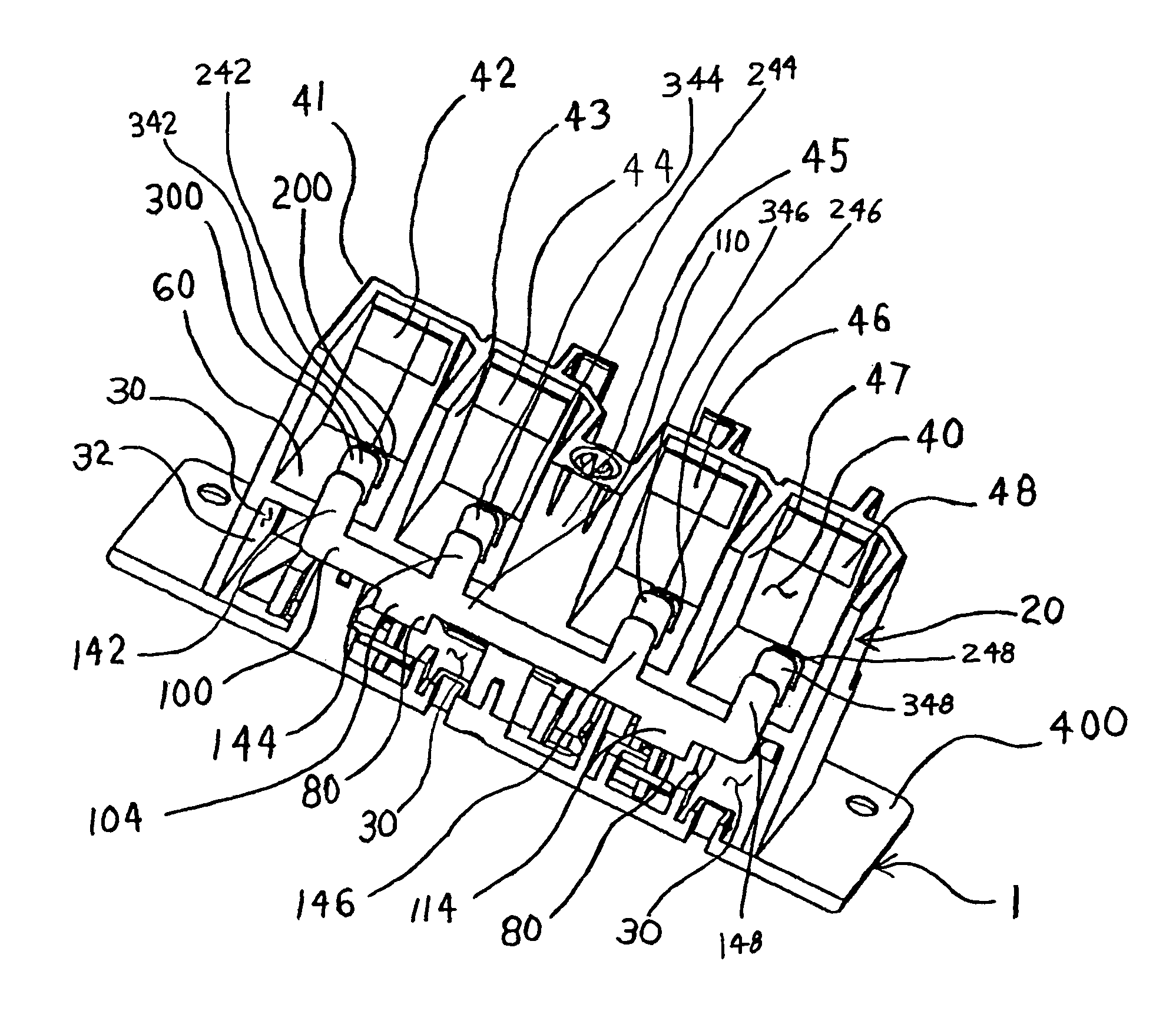
[0052]The enclosure 1 for electrical wiring devices of the present invention is designed to perform many functions. FIG. 4, shows four ports, 42, 44, 46 and 48 although the present invention can have just three rather than four ports. These ports will accept the new Q-CEB connector 2 which terminates the NM-B cable 4 (see FIG. 9) carrying the electric current or power to the wiring device and also carries the current back out of the device to another wiring device if needed in the electrical circuit.

[0053]Referring specifically to FIGS. 2, 3 and 4 the enclosure 1 of the present invention will be more fully described. The enclosure for wiring devices includes a housing member 20. Said housing member 20 has a main front chamber 30, a main rear chamber 40 and a central dividing wall 60 separating said main front chamber 30 fro...


PUM


Abstract

An enclosure for wiring devices such as switches and receptacles is provided. A housing member has a main front chamber, a main rear chamber and a central dividing wall separating the front chamber from the rear chamber. The housing has an open front leading to the front chamber. The rear chamber is divided into a plurality of electrical feed ports through which electrical power is provided to and may be taken from the enclosure. The feed ports each have an open back providing access to the ports but not to the main front chamber. A front plate member sized to completely cover and seal the open front of said front chamber is permanently attached to the housing to make a fully enclosed factory sealed enclosure in the front chamber. The front chamber contains a wiring device. Hot, neutral and ground busses extend between and interconnect the feed ports. These busses have segments extending through the dividing wall and connected to a wiring device. The present invention is designed primarily for safety but because of the use of fewer components and because of a greater ease of installation, significant labor savings also result from the present invention.

Description

BACKGROUND OF THE INVENTION[0001]1. Field of the Invention[0002]The present invention relates to an enclosure for electrical wiring devices. More specifically, it relates to an enclosure housing and mounting device for duplex receptacles, ground fault receptacles, switches, and dimmer controls.[0003]2. Description of the Prior Art[0004]Wiring devices such as a duplex outlet, a ground fault receptacle, a single pole or three way switch, dimmers, and the like are all electrical wiring devices that carry current or electricity to allow the consumer to conveniently control electrical current for use. These devices, because of their construction, have to be, by code, mounted in an enclosure or housing so that the device can be connected to electric cable which delivers the current to the device, and then mounted securely to the wall to complete installation. A prior art device in the form of a duplex receptacle mounted in a fixture box is shown in FIG. 1.[0005]A prior art enclosure 10 fo...

Claims


Application Information

Patent Timeline
Patent Type & Authority Patents(United States)
IPC IPC(8): H02G3/08
CPCH01R13/514H01R13/518H01R25/006H01R31/06H02G3/123H01R13/748
Inventor LIBBY, ROBERT A.LIBBY, II, CHARLES A.MASON, KYLEMONTGOMERY, DAVID E.
Owner ASLAN INDS
Why Eureka
Try Eureka